
Method for identifying blocked pressure lines

A pressure pipeline and pressure technology, which is used in the field of identifying blocked pressure pipelines, and can solve problems such as HWL dispensing and pressure pipeline blocking.

Active Publication Date: 2020-12-15
ROBERT BOSCH GMBH
View PDF3 Cites 0 Cited by
  • Summary
  • Abstract
  • Description
  • Claims
  • Application Information

AI Technical Summary

Problems solved by technology

It must therefore be taken into account that the pressure line may be blocked due to frozen HWL and therefore the HWL is not fitted into the exhaust system

Method used


Image

  • Method for identifying blocked pressure lines
  • Method for identifying blocked pressure lines
  • Method for identifying blocked pressure lines

Examples


Embodiment Construction

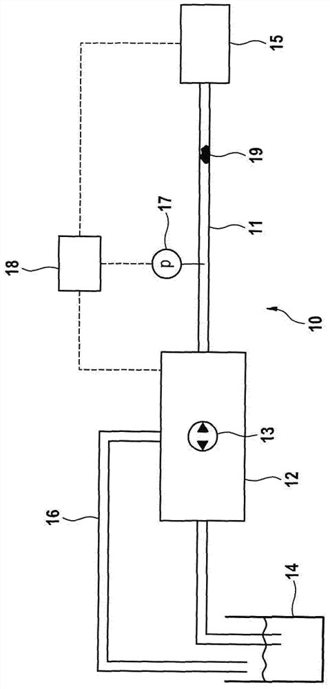
[0025] figure 1An SCR system 10 is shown for feeding reducing agent via a pressure line 11 into a not shown SCR catalytic converter. The SCR system 10 includes a delivery module 12 , which in turn includes a pump 13 , which is designed to deliver reducing agent out of a reducing agent tank 14 . The delivery module 12 is connected to the metering module 15 through the pressure pipeline 11, wherein the reducing agent is delivered from the delivery module 12 to the metering module 15 through the pressure pipeline 11, and the reducing agent in the metering module is subsequently Fitted into an exhaust system not shown. In addition, the SCR system 10 includes a return line 16 , which connects the delivery module 12 with the reducing agent storage tank 14 . The excess reducing agent is returned to the reducing agent storage tank 14 by the delivery module 12 . Furthermore, the pressure line 11 has a pressure sensor 17 which monitors the pressure p in the pressure line 11 and which...


PUM


Abstract

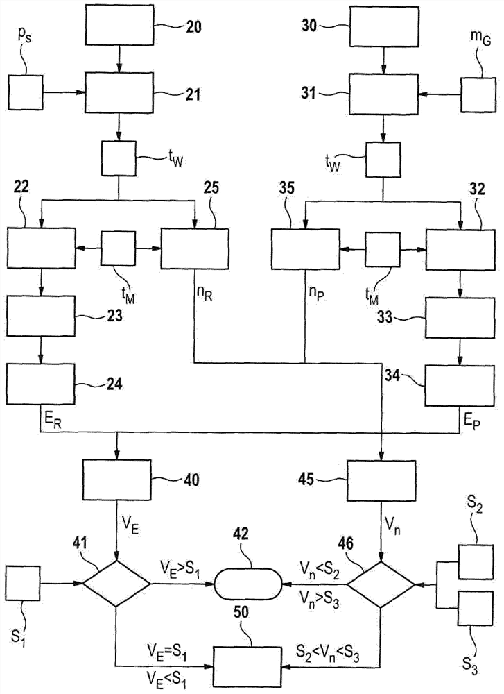
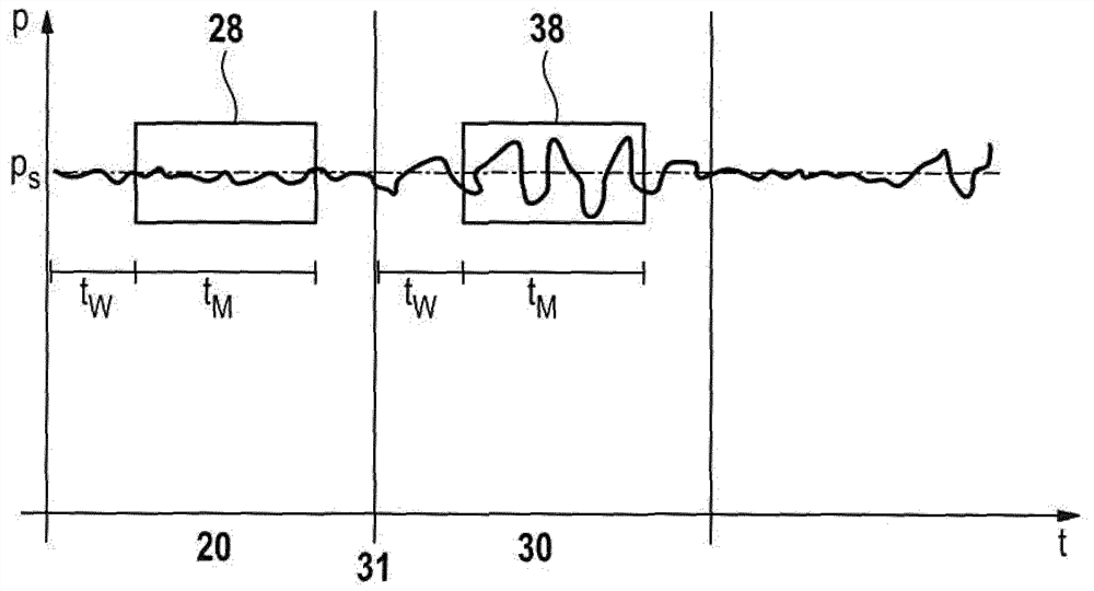
The invention relates to a method for detecting blocked pressure lines in an SCR system of an internal combustion engine. The SCR system has a transfer pump, a metering module and a pressure sensor. The method comprises the following steps: on the one hand, when the reducing agent solution is not added through the metering module, the measurement time (t M ) to measure a reference signal of the pressure (p) in the pressure line, and subsequently calculate the signal energy of the reference signal. On the other hand, during the metering time (t M ), and then calculate the signal energy of the pressure signal. Finally, the ratio of the signal energy of the pressure signal to the signal energy of the reference signal is calculated. If the ratio falls below a first predeterminable threshold value, a blocked pressure line is detected.

Description

technical field [0001] The invention relates to a method for detecting blocked pressure lines in an SCR system. Furthermore, the invention relates to a computer program which, when run on a computer, performs each step of the method, and a machine-readable storage medium storing the computer program. Finally, the invention relates to an electronic controller which is set up to carry out the method. Background technique [0002] Currently, the SCR-method ( S elective C analytic R reduction (selective catalytic reduction) for the reduction of nitrogen oxides (NOx) in exhaust gases. DE 103 46 220 A1 describes the underlying principle. In this case, a 32.5% urea-water solution (HWL), also known commercially as AdBlue®, is dosed into the oxygen-rich exhaust gas. A metering module is provided for this purpose, which includes nozzles for injecting the HWL into the exhaust gas flow. The HWL reacts in the SCR catalyst to form ammonia, which is then combined with nitrogen oxide...

Claims


Application Information

Patent Timeline
Patent Type & Authority Patents(China)
IPC IPC(8): F01N3/20F01N11/00
CPCF01N3/2066F01N3/208F01N11/00F01N2550/05F01N2610/02F01N2900/1808Y02T10/12Y02T10/40F01N2610/144F01N2610/148F01N2900/0416
Inventor A.布罗伊尔F.邓克
Owner ROBERT BOSCH GMBH
Learn More