
Driver circuit, converter electronics formed therewith and measuring system formed therewith

A drive circuit, voltage measurement technology, applied in the direction of measuring devices, measuring electrical variables, mass flow measuring devices, etc.

Active Publication Date: 2019-04-02
ENDRESS HAUSER FLOWTEC AG
View PDF90 Cites 3 Cited by
  • Summary
  • Abstract
  • Description
  • Claims
  • Application Information

AI Technical Summary

Problems solved by technology

[0008] However, this method or this circuit arrangement has the disadvantage that additional electronic components and components are required, such as, for example, for a measuring voltage proportional to the load current, which is passed through by the load current and thus reacts on the drive circuit. Sense resistors and at least two additional A / D sensors for digitizing the load current or load voltage, which again will increase the power requirements of the drive circuit even more

Method used


Image

  • Driver circuit, converter electronics formed therewith and measuring system formed therewith
  • Driver circuit, converter electronics formed therewith and measuring system formed therewith
  • Driver circuit, converter electronics formed therewith and measuring system formed therewith

Examples


Embodiment Construction

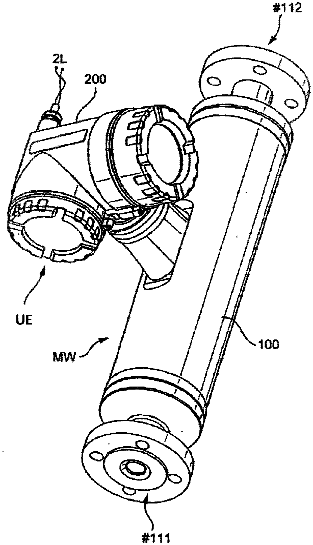
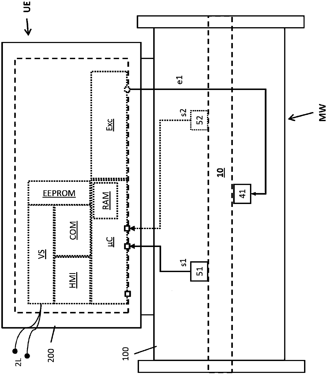
[0043] exist figure 1 or 2 shows that it can be connected to a (not shown) process circuit, for example in a pipeline of an industrial facility, for example by means of a Coriolis mass flow measuring device, a density measuring device, a viscosity measuring device or similar measuring devices Formed measuring system for flowable, in particular liquid or pourable media, which is used in the exemplary embodiment shown here for measuring and / or monitoring At least one further physical measured variable of the flowing medium, such as, for example, mass flow rate, density or viscosity or similar measured variables. The measuring system (here implemented in a compact manner by means of an in-line measuring device) comprises for this purpose a physical-electrical measuring transducer MW connected to the process line via inlet end #111 and outlet end #112, which The transducer is connected to the converter electronics UE of the measuring system, which is supplied with electrical ener...


PUM


Abstract

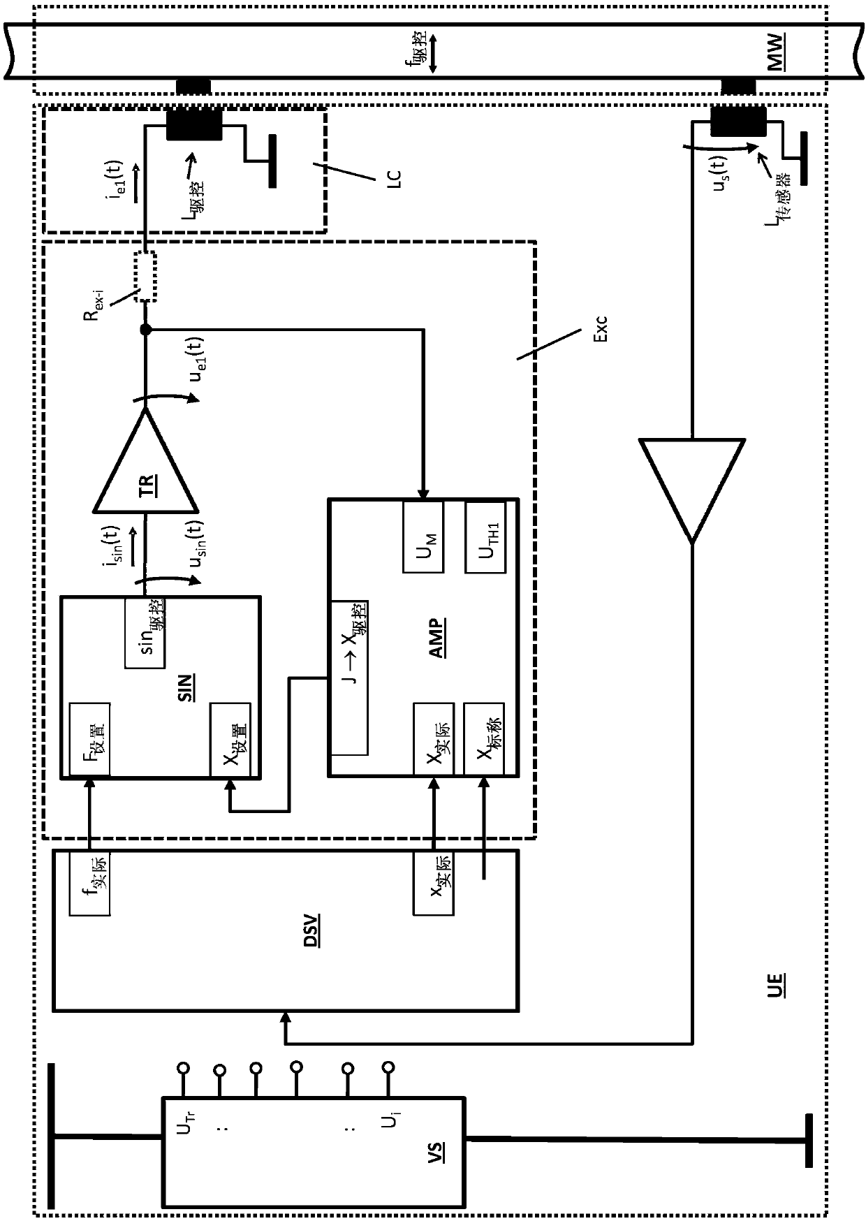
The driver circuit comprises a signal generator having a frequency control input, an amplitude control input and a signal output, an output stage having a signal input and a load output, and also an amplitude controller having an amplitude input, an amplitude output and a voltage measuring input. The signal generator is configured to output at the signal output thereof an at least occasionally periodic electrical analog signal having a signal frequency prescribed by a frequency control value present at the frequency control input, and having a voltage and / or current amplitude prescribed by anamplitude control value present at the amplitude control input. The output stage is configured, by means of an electrical circuit involving the selfsame load output, to drive a load current having a current intensity dependent on a signal voltage and / or a signal current of an electrical input signal present at the signal input and also to provide at the selfsame load output a load voltage having avoltage level dependent on the current intensity of the load current. Furthermore, the amplitude controller is configured to determine recurrently an amplitude deviation between an amplitude actual value present at the amplitude input and an amplitude setpoint value. Moreover, the amplitude controller is configured to determine recurrently an indicator value that signals whether an absolute valueof a measurement voltage present at the voltage measuring input is excessively high, namely whether the absolute value has exceeded a threshold value, and, using the indicator value, to determine anamplitude control value, in such a way that in the case where an absolute value of the measurement voltage is excessively high, successive amplitude control values of the amplitude control sequence are reduced, and also to output at the amplitude output an amplitude control sequence of amplitude control values calculated successively in time. The signal output of the signal generator in turn is electrically connected to the signal input of the output stage and the load output thereof is electrically connected to the voltage measuring input of the amplitude controller. Furthermore, the amplitude output of the amplitude controller is electrically connected to the amplitude control input of the signal generator.

Description

technical field [0001] The invention relates to a driver circuit for, in particular inductive, load circuits and to an especially intrinsically safe converter electronics resulting therefrom, or to a converter electronics having such a converter electronics, especially designed as a dual line field devices and / or vibratory (vibronisch) measuring systems. Background technique [0002] In industrial measurement and automation technology, measuring systems (so-called field devices) installed on-site or in the vicinity of the process are used to generate measured-value signals that represent measured variables in analog or digital form. The respective measured variable to be detected can be, for example, the mass flow rate or mass flow rate, density, viscosity, fill level or limit of a flowable or pourable, eg liquid, powdery, vaporous or gaseous medium. position, pressure, temperature, etc., the medium is guided or pre-stored in a corresponding process container, such as, for ...

Claims


Application Information

Patent Timeline
Patent Type & Authority Applications(China)
IPC IPC(8): G01F1/84
CPCG01F1/8431G01F1/8436G01F1/8413G01R27/00
Inventor 罗伯特·拉拉
Owner ENDRESS HAUSER FLOWTEC AG
Learn More