Tumbling-type stirring device and method

A stirring device and stirrer technology, which is applied in the direction of mixer accessories, chemical instruments and methods, transportation and packaging, etc., can solve the problem of inability to achieve macroscopic mixing effects at the same time, inability to achieve high conveying and stirring effects, and reduce the difficulty of making stirrers, etc. problems, to achieve the effects of convenient transportation and assembly, improved stirring stability and service life, and reduced assembly difficulty and labor costs

Pending Publication Date: 2019-04-05
上海林海生态技术股份有限公司 +1
View PDF12 Cites 1 Cited by
  • Summary
  • Abstract
  • Description
  • Claims
  • Application Information

AI Technical Summary

Problems solved by technology

However, this type of structure cannot achieve the improvement of the macroscopic mixing effect and the reduction of the difficulty of making the mixer at the same time.
[0004] For the raw materials located at the bottom of the mixing tank, in order to make them evenly mixed, two methods are generally adopted in the prior art: one is to set up a pipeline at the bottom of the mixing tank, and pump the raw materials to the top to continue stirring. The structure is complex, the cost is high, and it is not conducive to maintenance; the other is to directly set propeller blades or other curved surface blades in the mixing tank, such as the circulating mixer provided by the patent document CN104941486A, and the bottom raw materials are transported to the top through the blades , but due to the influence of liquid viscous force, the efficiency of upward transport is not high, especially for large-scale mixing equipment, when the fluid moves upward, it is easy to flow in the radial or circumferential direction, and cannot achieve high transport stirring effect

Method used


Image

  • Tumbling-type stirring device and method
  • Tumbling-type stirring device and method
  • Tumbling-type stirring device and method

Examples


Embodiment Construction

[0114] The present invention will be described in detail below in conjunction with specific embodiments. The following examples will help those skilled in the art to further understand the present invention, but do not limit the present invention in any form. It should be noted that those skilled in the art can make several modifications and improvements without departing from the concept of the present invention. These all belong to the protection scope of the present invention.

[0115] In describing the present invention, it is to be understood that the terms "upper", "lower", "front", "rear", "left", "right", "vertical", "horizontal", "top", The orientation or positional relationship indicated by "bottom", "inner", "outer", etc. is based on the orientation or positional relationship shown in the drawings, and is only for the convenience of describing the present invention and simplifying the description, rather than indicating or implying the referred device Or elements ...


PUM


Abstract

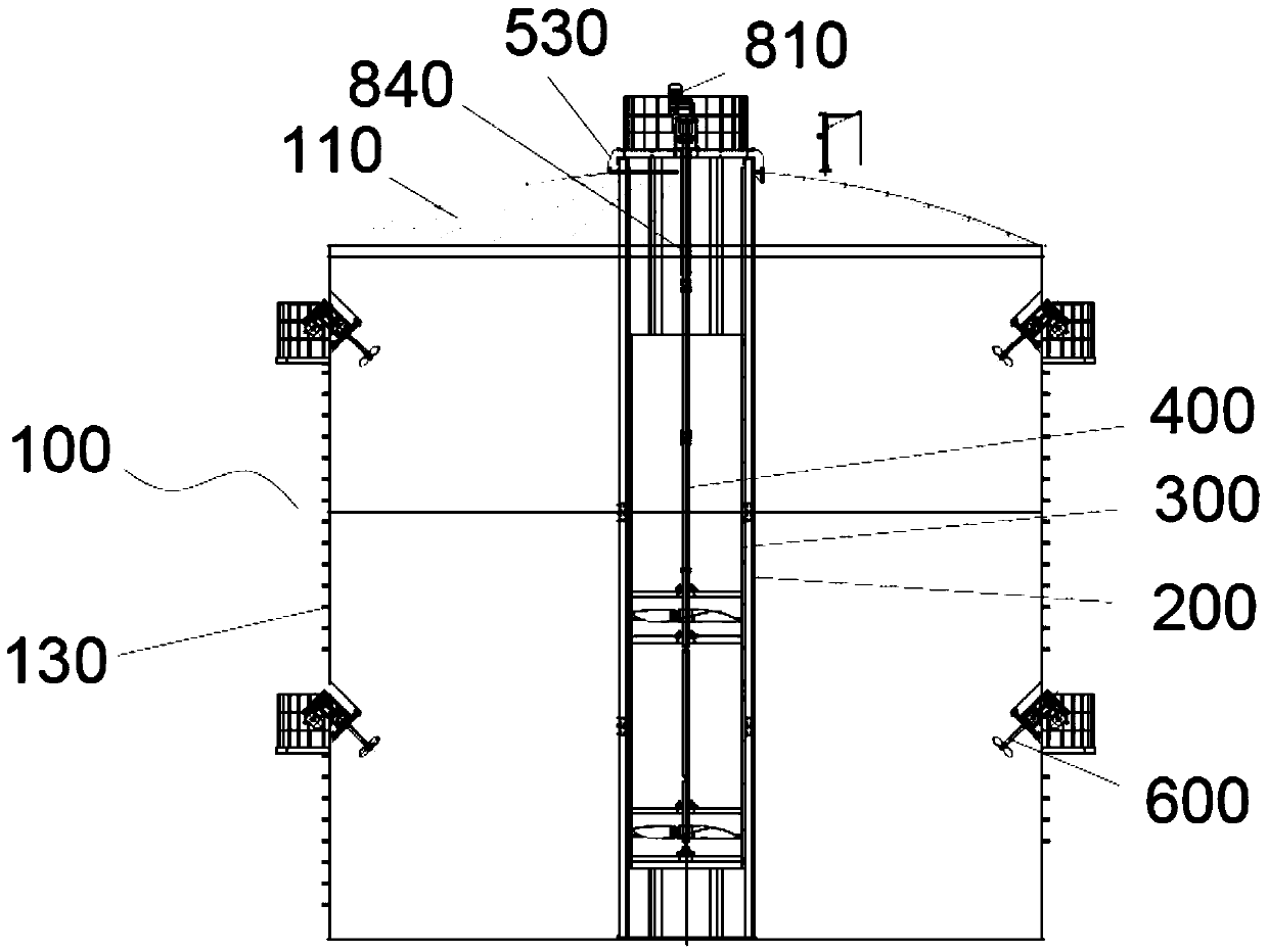
The invention provides a tumbling-type stirring device and method. The tumbling-type stirring device comprises a stirring tank, a center stirring system and a sidewall stirrer; a stirring space is formed in the stirring tank; the sidewall stirrer is mounted on the sidewall of a tank body of the stirring tank; the center stirring system includes a guide device and a center stirrer; the guide deviceincludes a guide barrel mounted in the stirring space; the center stirrer is extended along the length into the guide barrel; the sidewall stirrer is a structure to convey down the stirred material that is in the stirring space outside the guide barrel; the center stirrer is a structure to convey up the stirred material that is in the guide barrel. The sidewall stirrer and the center stirring system enable the stirred material to tumble up and down in the stirring tank; adding a pumping device to the outside of the stirring tank is not required; equipment cost is lowered, and stirring efficiency is effectively improved.

Description

technical field [0001] The invention relates to the field of stirring, in particular to a tumbling stirring device and a stirring method. Background technique [0002] The agitator is a device for forced convection and uniform mixing of liquid and gaseous media. The type, size and speed of the stirrer have an effect on the distribution of the stirring power between the bulk flow and the turbulent pulsations. Generally speaking, the power distribution of the turbine agitator is favorable for turbulent flow fluctuations, while the propeller agitator is favorable for the bulk flow. For the same type of agitator, under the condition of the same power consumption, the agitator with large diameter and low rotation speed mainly consumes power in the overall flow, which is conducive to macroscopic mixing. [0003] Most of the existing mixers are axial stirring, that is, the stirring shaft is parallel to the axis of the tank body, and on this basis, various structural deformations ...

Claims


Application Information

Patent Timeline
Patent Type & Authority Applications(China)
IPC IPC(8): B01F13/10B01F15/00
CPCB01F33/824B01F2035/351B01F35/43
Inventor 朱洪光
Owner 上海林海生态技术股份有限公司
Why Eureka
Try Eureka