Automatic punching device for processing parts

A punching device and parts processing technology, which is applied in the field of parts processing, can solve the problems of punching position deviation and low degree of automation, and achieve the effect of high punching precision, high degree of automation, and good punching effect

Inactive Publication Date: 2019-04-05
泰州市津专知识产权服务有限公司
5 Cites 25 Cited by

AI-Extracted Technical Summary

Problems solved by technology

[0004] In the process of part processing, it is often necessary to use a punching device for equidistant punching, especially when drilling in the circumferential direction. The e...

Method used

A kind of automatic punching device for parts processing, comprising base plate 1, support 2, placement table 3, two-way threaded rod 10 and transmission chamber 19; The right end of described workbench 1 is provided with transmission chamber 19, and transmission chamber 19 inside A bevel gear D24 is provided, and the rotating shaft of the bevel gear D24 runs through the transmission chamber 19 to the upper end of the workbench 1 and is fixedly connected to the lower end of the placing table 3. The upper end of the placing table 3 is provided with a fixing mechanism, and the setting of the fixing mechanism is to fix the plate , to prevent the plate from moving during the punching process.
It should be noted that what the reversing motor 11 adopted is a 4IK/80YYJT model motor, and the performance of the sign...

Abstract

The invention discloses an automatic punching device for processing parts. The automatic punching device comprises a bottom plate, a bracket, a placing table, a bidirectional threaded rod and a transmission cavity; the right end of a working table is provided with a transmission cavity, a bevel gear D is arranged on the inner side of the transmission cavity, a rotating shaft of the bevel gear D penetrates through the transmission cavity to reach the upper end of the working table and to be fixedly connected with the lower end of the placing table, and the upper end of the placing table is provided with a fixing mechanism. The automatic punching device is novel in design, when a push plate moves downwards, a rack plate is driven by a connecting rod to move downwards, when the rack plate moves downwards, an annular gear on a third rotating rod drives ratchet teeth to rotate, the ratchet teeth cannot drive a second rotating rod to rotate under the effect of pawls, after punching is completed, a positive and negative rotation motor rotates reversely, at the time, the push plate moves upwards, rotation of the second rotating rod is achieved, the placing table is driven to be rotated under the effects of a bevel gear C and the bevel gear D, rotation of part plates is achieved, automatic transposition and punching are achieved, and the automation degree is high.

Application Domain

Technology Topic

Image

  • Automatic punching device for processing parts
  • Automatic punching device for processing parts
  • Automatic punching device for processing parts

Examples

  • Experimental program(1)

Example Embodiment

[0029] Example two
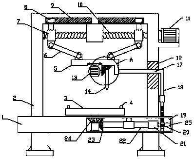
[0030] An automatic punching device for parts processing, comprising a bottom plate 1, a support 2, a placing table 3, a two-way threaded rod 10 and a transmission cavity 19; the right end of the worktable 1 is provided with a transmission cavity 19, and the inner side of the transmission cavity 19 is provided with a cone The rotating shaft of the gear D24 and the bevel gear D24 penetrates the transmission cavity 19 to the upper end of the worktable 1 and is fixedly connected to the lower end of the placing table 3. The upper end of the placing table 3 is provided with a fixing mechanism which is set to fix the plate and prevent the plate Movement occurs during the punching process.
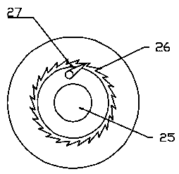
[0031] The right end of the bevel gear D24 is meshed with a bevel gear C23, and the bevel gear C23 is fixedly connected to the outer side of the ratchet mechanism 21 through the second rotating rod 22. Preferably, the ratchet mechanism 21 includes a ratchet tooth 26 and a pawl 27. 26 is fixedly installed on the inner side of the ratchet mechanism 21, the pawl 27 is rotatably connected to the third rotating rod 25 through a torsion spring, and the right end of the third rotating rod 25 is rotatably connected to the inner side of the transmission cavity 29. When the third rotating rod 25 rotates forward The ratchet mechanism 21 drives the second rotating rod 22 to rotate, and the second rotating rod 22 rotates the placing table 3 through the engagement of the bevel gear C23 and the bevel gear D24.
[0032] A through groove is symmetrically provided on the side wall of the transmission cavity 19, and a rack plate 18 is slidably connected in the through groove. The front end of the rack plate 28 meshes with the ring gear 20 fixedly mounted on the third rotating rod 25. When the plate 28 moves up and down, the ring gear 20 drives the third rotating rod 25 forward and backward.
[0033] A bracket 2 is fixedly installed at the upper end of the bottom plate 1, and a drive mechanism is arranged on the bracket 2. The drive mechanism is a hydraulic telescopic rod. The upper and lower ends of the hydraulic telescopic rod are respectively fixed to the support 2 and the push plate 5; the lower end of the push plate 5 is connected to There is a drill bit 14, a bevel gear A15 is fixedly installed on the drill bit 14, and the left end of the bevel gear A15 is meshed with a bevel gear B16 fixed on the output shaft of the motor 13. When the motor 13 rotates, the bevel gear A15 and the bevel gear B16 are engaged to drive the bit 14 rotation to achieve drilling.
[0034] It should be noted that the forward and reverse motor 11 uses a 4IK/80YYJT motor. The signal motor has stable performance. Other types of motors can also be used as long as they meet the driving requirements. The comparison in this application is not limited. The motor 13 uses It is Y-160M ​​2-2 model motor, other models can also be used, as long as it meets the driving requirements, this application is not limited for comparison.
[0035] The right end of the pushing plate 5 is fixed with a connecting rod 17, and the end of the connecting rod 17 away from the pushing plate 5 penetrates the through slot 12 provided on the bracket 2 at the right end and is fixedly connected with the rack plate 18, and the pushing plate 5 passes through The connecting rod 17 drives the rack plate 18 to move up and down.
[0036] The working principle of the present invention is: place the parts to be processed on the placing table 3 and fix it by the fixing mechanism 4 so that the first position to be punched is located directly under the drill bit 14, the motor 13 is started, and the motor 13 passes when it rotates. The meshing effect of bevel gear A15 and bevel gear B16 drives the drill bit 14 to rotate, and at the same time, the forward and reverse motor 11 is started to rotate forward. The forward and reverse motor 11 drives the two-way threaded rod 10 to rotate. The two-way threaded rod 10 rotates through the threaded sleeve 7 and pushes The action of the rod 6 drives the push plate 5 and the drill bit 14 to move downwards synchronously, so as to achieve the requirement of drilling. When the push plate 5 moves down, the connecting rod 17 drives the rack plate 18 to move down, and the rack plate 18 moves down. When the ring gear 20 on the third rotating rod 25 drives the ratchet teeth 26 to rotate, the ratchet teeth 26 cannot drive the second rotating rod 22 to rotate under the action of the pawl 27. When the punching is completed, the forward and reverse motor 11 reverses. At this time, the pushing plate 5 moves upward, and the rack plate 18 is driven to move upward through the connecting rod 17. When the rack plate 18 moves upward, the ring gear 20 on the third rotating rod 25 drives the ratchet teeth 26 to rotate. The pawl 27 drives the second rotating rod 22 to rotate. When the third rotating rod 22 rotates, the bevel gear C23 and the bevel gear D24 are engaged to drive the placement table 3 to rotate, thereby realizing automatic transposition drilling and high drilling efficiency .

PUM

no PUM

Description & Claims & Application Information

We can also present the details of the Description, Claims and Application information to help users get a comprehensive understanding of the technical details of the patent, such as background art, summary of invention, brief description of drawings, description of embodiments, and other original content. On the other hand, users can also determine the specific scope of protection of the technology through the list of claims; as well as understand the changes in the life cycle of the technology with the presentation of the patent timeline. Login to view more.

Similar technology patents

Classification and recommendation of technical efficacy words

  • Improve drilling accuracy
  • High degree of automation

Perforating device with high accuracy

Owner:安徽英杰精工机械股份有限公司

Full-automatic flexible assembly line of light emitting diode (LED) bulb lamp

InactiveCN102896494AIncreased reliability and automationHigh degree of automationAssembly machinesLight sourceStructure based
Owner:SHANGHAI RADIO EQUIP RES INST
Why Eureka
Try Eureka