Carbon deposit suction device of electric spark forming machine

A technology of adsorption device and molding machine, which is applied in attachment devices, electric processing equipment, metal processing equipment, etc., can solve problems such as scrapping and rework of workpieces, and achieve the effects of easy flushing, increased flow rate and impact force.

Inactive Publication Date: 2019-04-05
WUJIANG TIANLONG MACHINERY
View PDF8 Cites 1 Cited by
  • Summary
  • Abstract
  • Description
  • Claims
  • Application Information

AI Technical Summary

Problems solved by technology

[0002] During the discharge process of the EDM machine, the high temperature makes the surface of the workpiece melt and gasify, and splashes explosively into the machining fluid, and quickly solidifies into discharge slag, which is taken away by the flowing spark oil. However, when the metal between the electrode and the workpiece When the particles are not completely taken away by the machining fluid, the power is turned on again. At this time, the instantaneous high temperature will cause a bump on the surface of the workpiece, forming carbon deposits, which will cause the workpiece to be reworked or even scrapped. For this reason, we propose a product for EDM Carbon adsorption device is used to solve the above problems

Method used


Image

  • Carbon deposit suction device of electric spark forming machine
  • Carbon deposit suction device of electric spark forming machine
  • Carbon deposit suction device of electric spark forming machine

Examples


Embodiment Construction

[0016] The following will clearly and completely describe the technical solutions in the embodiments of the present invention with reference to the accompanying drawings in the embodiments of the present invention. Obviously, the described embodiments are only some, not all, embodiments of the present invention. Based on the embodiments of the present invention, all other embodiments obtained by persons of ordinary skill in the art without making creative efforts belong to the protection scope of the present invention.

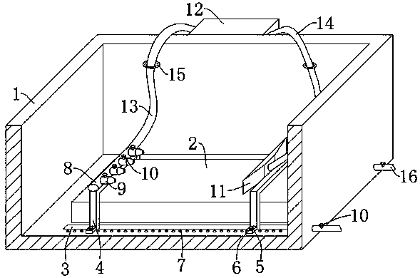
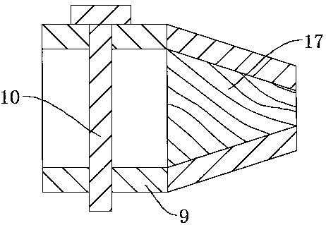
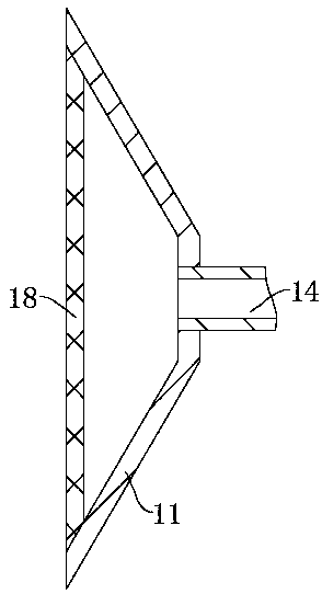
[0017] see Figure 1-5 , the present invention provides a technical solution: a carbon deposition adsorption device for an electric discharge forming machine, including a working tank 1, a workbench 2 is fixedly installed on the inner bottom plate of the working tank 1, and the bottom plate of the working tank 1 on both sides of the workbench 2 is provided with The chute 3 and both ends of the chute 3 are slidingly clamped to the sliding frame 4, and the outer...


PUM


Abstract

The invention discloses a carbon deposit suction device of an electric spark forming machine. The carbon deposit suction device of the electric spark forming machine comprises a working trough. A workbench is installed on a base plate in the working trough. Sliding grooves are formed in the base plate of the working trough and on the two sides of the workbench. Sliding racks are arranged at the ends of the sliding grooves in a clamping connection manner. A positioning plate is installed on the outer wall of each sliding rack. Multiple threaded holes are formed in the base plate of the workingtrough. Positioning bolts penetrate through the positioning plates. The positioning bolts are connected with the threaded holes through thread structures. An oil distribution tube and an oil suction disk are installed on the sliding racks respectively. The oil distribution tube is connected with multiple nozzles in a sleeving manner. An installation box is installed on the outer wall of the working trough. An oil pump is installed in the installation box. One end of the oil pump communicates with the oil distribution tube through an oil outlet tube, and the other end of the oil pump communicates with the oil suction disk through an oil suction tube. When one workpiece is fixed to the workbench, the sliding racks are enabled to slide to make the nozzles and the oil suction disk be located on the two sides of the part, to be machined, of the workpiece, and are fixed by the positioning bolts and the threaded holes, spark oil ejected out of the nozzles washes away electric slag and carbondeposit generated at the machined part of the workpiece, and the oil suction disk sucks the electric slag and carbon deposit away from the workpiece.

Description

technical field [0001] The invention relates to the technical field of electric discharge machining equipment, in particular to a carbon deposition adsorption device for electric discharge forming machines. Background technique [0002] During the discharge process of the EDM machine, the high temperature makes the surface of the workpiece melt and gasify, and splashes explosively into the machining fluid, and quickly solidifies into discharge slag, which is taken away by the flowing spark oil. However, when the metal between the electrode and the workpiece When the particles are not completely taken away by the machining fluid, the power is turned on again. At this time, the instantaneous high temperature will cause a bump on the surface of the workpiece, forming carbon deposits, which will cause the workpiece to be reworked or even scrapped. For this reason, we propose a product for EDM A carbon adsorption device is used to solve the above-mentioned problems. Contents of...

Claims


Application Information

Patent Timeline
Patent Type & Authority Applications(China)
IPC IPC(8): B23H1/00B23H11/00
CPCB23H1/00B23H11/00
Inventor 施国春
Owner WUJIANG TIANLONG MACHINERY
Why Eureka
Try Eureka