Optical lens grinding machine

A technology for optical lenses and grinding machines, which is applied to optical surface grinders, optics, and optical components. It can solve the problems of expensive equipment, complicated replacement parts, and complex structures, so as to improve operating efficiency, avoid collision wear, and reduce operating manpower. Effect

Inactive Publication Date: 2019-04-05
中山容大光学科技有限公司
View PDF6 Cites 12 Cited by
  • Summary
  • Abstract
  • Description
  • Claims
  • Application Information

AI Technical Summary

Problems solved by technology

However, some polishing equipment currently on the market are often large in size and complex in structure. When the equipment fails, it is complicated to replace parts, and the equipment is expensive, and the purchase cost and maintenance cost are relatively high.
[0003] Chinese patent (authorized announcement number: CN208084027U) discloses a fine grinding device for lens polishing. During the grinding process, the device will also add polishing liquid and po...

Method used


Image

  • Optical lens grinding machine
  • Optical lens grinding machine
  • Optical lens grinding machine

Examples


Embodiment 1

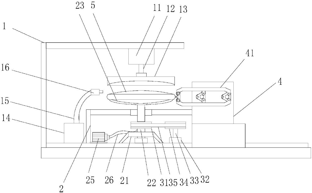
[0027] see figure 1 , an optical lens grinding machine, comprising a frame 1, a transmission frame 2 is installed on the bottom plate of the frame 1, a support column 22 is vertically installed on the transmission frame 2, and the bottom end of the support column 22 passes through The bearing is installed on the bottom plate of the frame 1, and the bottom end of the support column 22 is equipped with a support frame 21. The support frame 21 is inclined to support and the end is fixed on the bottom plate of the frame 1. The support mechanism ensures that the support column 22 stability.

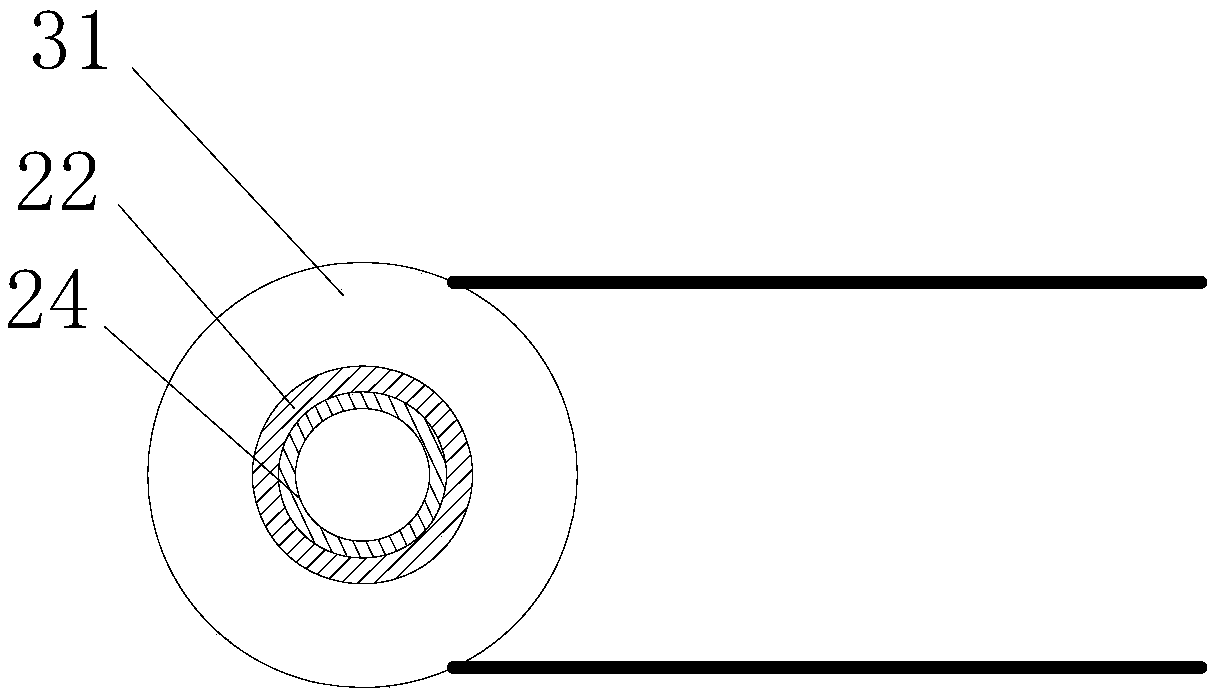
[0028] see figure 1 and figure 2 , the top of the support column 22 is equipped with a suction cup 23, the support column 22 is a hollow structure, the inner cavity of the support column 22 is provided with an air suction pipe 24, and the transmission frame 2 is equipped with an air suction pump 25, The suction end of the suction pump 25 is equipped with an air guide pipe 26, the bottom en...

Embodiment 2

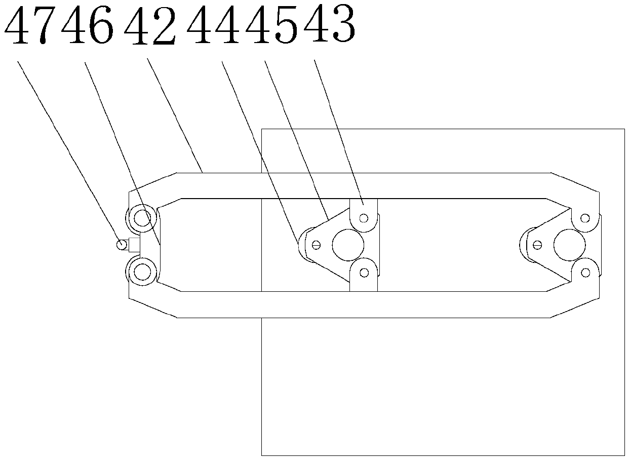
[0033] see figure 1 and image 3 , this embodiment is a further optimization of Embodiment 1. On the basis of it, a side machine 4 is installed on the side of the frame 1, and a side grinding frame 41 is installed on the side machine 4. The side The edge grinding frame 41 comprises a transmission link 42, and the transmission link 42 is respectively located on the upper and lower sides and is equipped with a fixed rod 43. A tripod 45 is installed between the transmission connecting rods 42 on both sides, and the tripod 45 is an isosceles triangle structure, and the fixed rods 43 are installed at the adjacent bottom corners of the tripod 45 respectively, and the transmission connecting rod 42 The front end of the grinding seat 46 is equipped with a grinding seat 46, the upper and lower ends of the grinding seat 46 are connected with the transmission connecting rod 42 by locking bolts, and the front end of the grinding seat 46 is equipped with a grinding head 47. Drive motors ...


PUM


Abstract

The invention relates to the technical field of lens processing, and in particular to an optical lens grinding machine. The optical lens grinding machine comprises a machine frame, wherein a transmission frame is mounted on a bottom plate of the machine frame; a supporting column is vertically mounted on the transmission frame; the bottom end of the supporting column is mounted on the bottom plateof the machine frame through a bearing; a sucker is mounted at the top end of the supporting column; the supporting column adopts a hollow structure; an air suction pipe is arranged in an inner cavity of the supporting column; an air suction pump is mounted on the transmission frame; an air guiding pipe is mounted at the air suction end of the air suction pump; the bottom end of the air suction pipe is connected with the air guiding pipe; a driven wheel is mounted on the supporting column; a transmission motor is mounted on the bottom plate of the machine frame; a transmission rotating shaftis mounted at the driving end of the transmission motor; and a transmission wheel is mounted at the top end of the transmission rotating shaft, and is connected with the driven wheel through a transmission belt. According to the optical lens grinding machine disclosed by the application, flank grinding operation and mirror polishing operation are synchronously performed, so that the effect of single-station multi-angle processing is achieved.

Description

technical field [0001] The invention relates to the technical field of lens processing, in particular to an optical lens grinding machine. Background technique [0002] In daily life, the application of optical lenses can be seen everywhere. In recent years, as people have higher and higher requirements for the smoothness and precision of optical lenses, the requirements for operating equipment and operating processes in the production process are also getting higher and higher. . In the production and processing of optical lenses, polishing is one of the very important processes. The quality of polishing and the level of efficiency directly affect the cost of production. However, some polishing equipment currently on the market are often bulky and complex in structure, and it is complicated to replace parts when the equipment fails, and the equipment is expensive, and the purchase cost and maintenance cost are relatively high. [0003] Chinese patent (authorized announcem...

Claims


Application Information

Patent Timeline
IPC IPC(8): B24B13/00B24B13/005B24B9/14B24B27/00
CPCB24B9/14B24B9/146B24B13/00B24B13/0055B24B27/0076B24B27/0092
Inventor 张杰
Owner 中山容大光学科技有限公司
Why Eureka
Try Eureka