Planning method of laser deposition scanning path

A scanning path and laser deposition technology, applied in the field of additive manufacturing, can solve problems such as affecting the bonding between the original layer and the replica layer, low forming efficiency, affecting forming speed efficiency and quality, etc.

Inactive Publication Date: 2019-04-05
TSC LASER TECH DEV BEIJING CO LTD
View PDF5 Cites 2 Cited by
  • Summary
  • Abstract
  • Description
  • Claims
  • Application Information

AI Technical Summary

Problems solved by technology

[0002] After the parts are layered and sliced, the program automatically sorts the cutting areas of each slice layer. The default sorting method is irregular, and there are many empty paths of the equipment. Some areas have serious heat accumulation, which affects the forming speed, efficiency and quality, it is necessary to manually ad

Method used


Image

  • Planning method of laser deposition scanning path
  • Planning method of laser deposition scanning path
  • Planning method of laser deposition scanning path

Examples


Embodiment Construction

[0033] The present invention will be further described in detail below in conjunction with the examples, but not limited thereto.

[0034] In order to solve the problems of low forming efficiency and poor quality of parts, the present invention provides a laser deposition scanning path planning method.

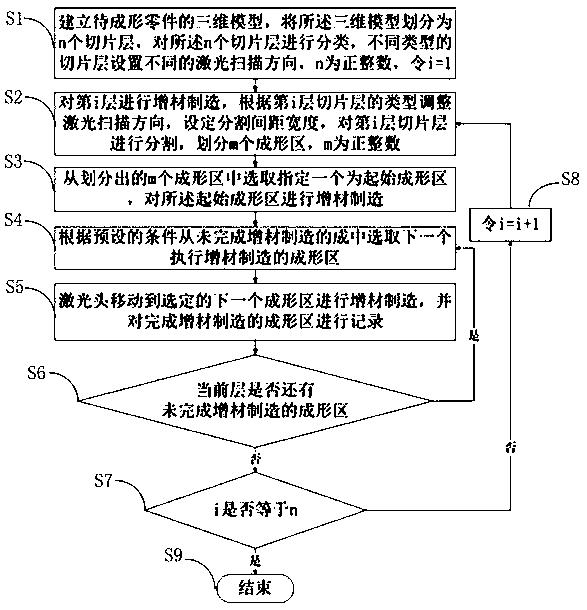
[0035] like figure 1 As shown, a laser deposition scanning path planning method provided by the present invention is characterized in that it includes the following steps:

[0036] S1. Establish a three-dimensional model of the part to be formed, divide the three-dimensional model into n slice layers, classify the n slice layers, set different laser scanning directions for different types of slice layers, n is a positive integer, let i=1;

[0037] Wherein, the concrete steps of step S1 are:

[0038] S101, using 3D software to establish a 3D model of the part to be formed;

[0039] S102. Layer and slice the three-dimensional model, divide it into n slice layers, number the s...


PUM


Abstract

The invention relates to a planning method of a laser deposition scanning path. Three standards of radius, temperature and distance of a selected area are utilized to select a forming area for additive manufacturing, and the sequence of the forming area is controlled, so that an invalid stroke is avoided, heat input is reduced to the maximum, and the forming efficiency is improved. The scanning direction of a laser head is adjusted at 90 degrees for additive manufacturing, so that the bondability between layers is increased, and the quality of parts is increased.

Description

technical field [0001] The invention relates to the technical field of additive manufacturing, in particular to a laser deposition scanning path planning method. Background technique [0002] After the parts are layered and sliced, the program automatically sorts the cutting areas of each slice layer. The default sorting method is irregular, and there are many empty paths of the equipment. Some areas have serious heat accumulation, which affects the forming speed, efficiency and Quality requires manual adjustment of the order of the cutting areas, which requires a lot of work, and the scanning trajectory overlap rate between the original layer and the copied layer is high, which affects the combination between the original layer and the copied layer. Therefore, the traditional method has the problems of low forming efficiency and poor part quality. Contents of the invention [0003] In view of the above technical problems, the present invention provides a laser deposition...

Claims


Application Information

Patent Timeline
IPC IPC(8): B29C64/153B29C64/386B33Y10/00B33Y50/00
CPCB29C64/153B29C64/386B33Y10/00B33Y50/00
Inventor 王跃岭葛青刘斌高佩宝
Owner TSC LASER TECH DEV BEIJING CO LTD
Why Eureka
Try Eureka