Monorail crane self-balancing compensation heavy hydraulic lifting beam

A technology of self-balancing and lifting beams, which is applied in the direction of track system, load hanging components, safety devices, etc., can solve the problems that the carrying capacity is not as good as the surface contact, cannot transport the hydraulic support, and the safety is not guaranteed, so as to increase the carrying capacity, The effect of smooth and safe transportation, guarantee of life and property safety

Pending Publication Date: 2019-04-05
SCHARF MINING MACHINERY XUZHOU
View PDF6 Cites 2 Cited by
  • Summary
  • Abstract
  • Description
  • Claims
  • Application Information

AI Technical Summary

Problems solved by technology

[0004] like figure 2 Shown is the existing second type of lifting beam. Although there are four lifting points, on the one hand, there is no guard plate protection, and the safety is not guaranteed;
[0005] like image 3 Shown is the existing third type of lifting beam, which uses oil cylinders to lift. The stroke of the oil cylinder limits the height of the load and cannot transport high hydraulic supports; on the other hand, the upper part of the oil cylinder is a chain. This form of design Swinging during transportation is inevitable, and what’s more, the hydraulic support may even tilt back during the uphill process, which poses a huge safety hazard
[0006] To sum up: the above-mentioned lifting girder longitudinal beams and beams are all in line contact. On the one hand, the bearing capacity of the line contact is not as good as that of the surface contact. On the other hand, the line contact is not stable enough during the operation process, and it may tilt back These conditions that are prone to safety accidents

Method used


Image

  • Monorail crane self-balancing compensation heavy hydraulic lifting beam
  • Monorail crane self-balancing compensation heavy hydraulic lifting beam
  • Monorail crane self-balancing compensation heavy hydraulic lifting beam

Examples


Embodiment Construction

[0027] The following will clearly and completely describe the technical solutions in the embodiments of the present invention with reference to the accompanying drawings in the embodiments of the present invention. Obviously, the described embodiments are only some, not all, embodiments of the present invention. Based on the embodiments of the present invention, all other embodiments obtained by persons of ordinary skill in the art without making creative efforts belong to the protection scope of the present invention.

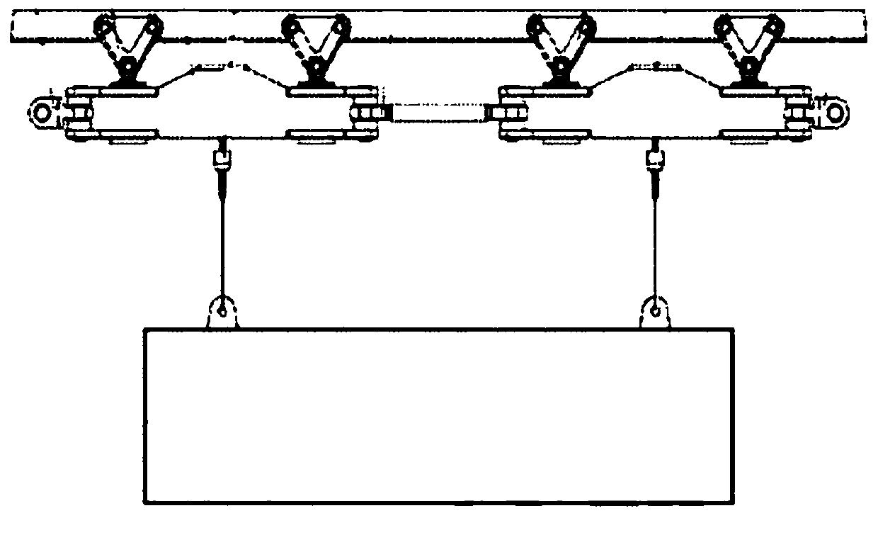
[0028] like Figure 4 to Figure 5 , the present invention proposes a monorail crane self-balancing compensation heavy-duty hydraulic lifting beam, which includes: an arched beam 1, a beam 2, a longitudinal beam 3, and a connecting pin 5 between the beam and the longitudinal beam as the main body of the lifting beam;

[0029] Described arched crossbeam 1 comprises crossbeam main body 1-1, walking trolley fixed beam 1-2 and walking trolley 1-3; Crossbeam main bo...


PUM


Abstract

The invention discloses a monorail crane self-balancing compensation heavy hydraulic lifting beam. The monorail crane self-balancing compensation heavy hydraulic lifting beam comprises an arched beam(1), a beam (2), a longitudinal beam (3) and beam and longitudinal beam connecting pins (5), wherein the arched beam (1) is used as the main bearing body of the lifting beam. Each beam and longitudinal beam connecting pin (5) is a pin with both a cylindrical surface and a spherical surface, wherein the cylindrical surface is connected with the beam (2) in the axial direction, the spherical surfaceis connected with the longitudinal beam (3) in the normal direction, and self-balancing compensation connection is formed. According to the monorail crane self-balancing compensation heavy hydrauliclifting beam, the longitudinal beam (3) is adjusted in any direction along the spherical surface of each beam and longitudinal beam connecting pin (5) under the action of gravity of load, and guarantees surface contact at any time, the longitudinal beam carries out self adjustment fix the load at the position where the gravity center of the load is more stable, it is avoided that the load swings because of unstable gravity center, and self-balancing compensation of the lifting beam itself is achieved.

Description

technical field [0001] The invention relates to a diesel engine monorail crane system suitable for underground coal mines, in particular to a monorail crane self-balancing compensation heavy-duty hydraulic lifting beam. Background technique [0002] The diesel engine monorail crane system is an auxiliary underground transportation system, which is mainly used for the system that runs on the track installed on the top space when the floor condition is not good. Since the floor condition is not good, the transportation of large equipment such as hydraulic supports needs to be completed by the diesel engine monorail system. Since the hydraulic support usually weighs 20 to 30 tons, the carrying capacity of the lifting beam is the primary condition for the selection of the lifting beam. The shape of the hydraulic support is irregular, and the traditional two-point lifting beam cannot be hoisted at all. The most common problem encountered during the hoisting process of the ordina...

Claims


Application Information

Patent Timeline
Patent Type & Authority Applications(China)
IPC IPC(8): B66C7/08B66C9/10B66C13/06B66C15/00
CPCB66C7/08B66C9/10B66C13/06B66C15/00
Inventor 范芳飞李节李军伟宋冠军朱鹏苗生汪秀杜建宾
Owner SCHARF MINING MACHINERY XUZHOU
Why Eureka
Try Eureka