Hollow cathode discharge system and method for preparing diamond-like film

A hollow cathode discharge, diamond thin film technology, applied in metal material coating process, gaseous chemical plating, coating and other directions, can solve the problem of unfavorable high-efficiency deposition of diamond-like carbon film, reduction of plasma density, and unfavorable large-area deposition of diamond-like carbon film. and other problems, to achieve the effect of improving deposition area and deposition efficiency, optimizing surface characteristics and excellent hardness

Inactive Publication Date: 2019-04-05
BEIJING UNIVERSITY OF CIVIL ENGINEERING AND ARCHITECTURE
View PDF8 Cites 2 Cited by
  • Summary
  • Abstract
  • Description
  • Claims
  • Application Information

AI Technical Summary

Problems solved by technology

For example, the cylindrical hollow cathode in the prior art has an adjustable diameter, but if the aperture exceeds three times the sheath width, the plasma density will be reduced, which is not conducive to

Method used


Image

  • Hollow cathode discharge system and method for preparing diamond-like film
  • Hollow cathode discharge system and method for preparing diamond-like film
  • Hollow cathode discharge system and method for preparing diamond-like film

Examples


Example Embodiment

[0048] Example one

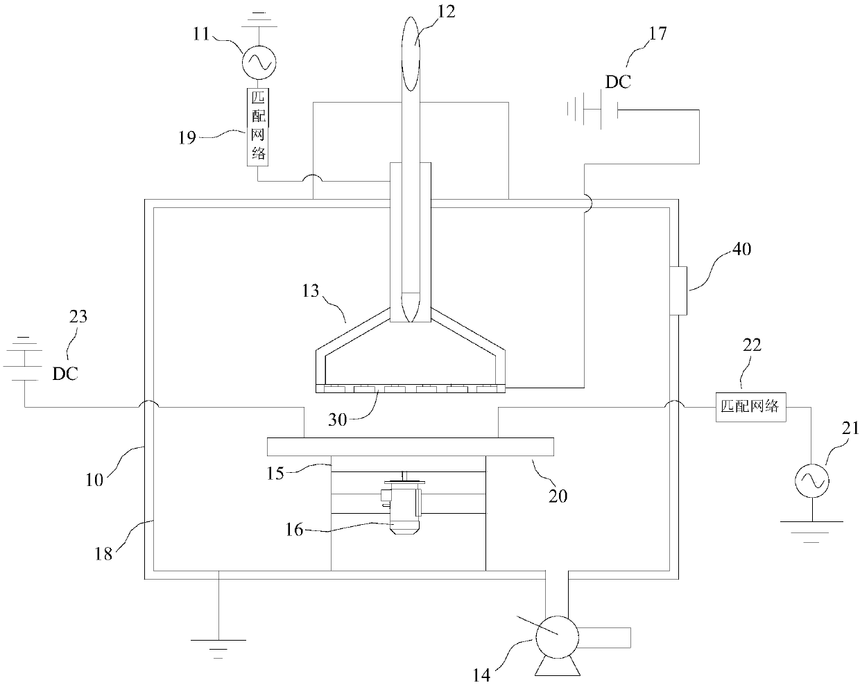
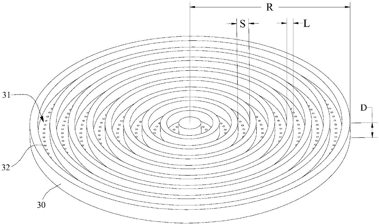
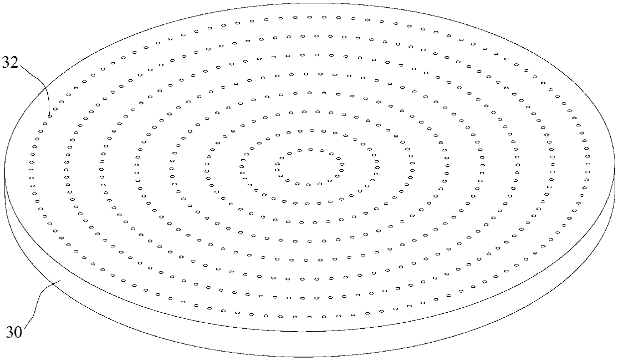
[0049] A hollow cathode discharge system was used to deposit the DLC film. The distance between the hollow cathode 30 and the anode 20 was 3 cm. The substrate was placed on the anode 20 and vacuumed to 10 -6 Torr, add argon gas to 10 Pa, turn on the cathode RF power supply 11 and the anode RF power supply 21 and anode DC power supply 23 on the anode 20, plasma clean the substrate for 10 minutes, after cleaning, vacuum again to 10 - 6 Torr, a mixed gas of argon and acetylene is introduced, the flow rate of argon is 400 sccm, and the flow rate of acetylene is 100 sccm. Adjust the pressure of the vacuum chamber to 10 Pa, start to deposit the DLC film, and the reaction time is 2 hours to obtain the substrate on which the DLC film is deposited. In this embodiment, the thickness D of the hollow cathode 30 is 20mm, the width S of the annular groove 31 is 5mm, the gap L between adjacent annular grooves 31 is 5mm, the depth of the annular groove 31 is 15mm, and the rad...

Example

[0050] Examples two to five

[0051] The other experimental conditions are equivalent to those of the first embodiment. The difference is that the radius R of the hollow cathode 30 is 60mm, 80mm, 120mm and 140mm, respectively. The physical and chemical properties of the substrate surface of the deposited DLC film obtained in each embodiment are tested. , The performance of the substrate of the DLC film of each embodiment is equivalent.


PUM

PropertyMeasurementUnit
Radiusaaaaaaaaaa

Abstract

The embodiment of the invention relates to the technical field of film preparation, in particular to a hollow cathode discharge system which comprises a vacuum chamber, wherein an anode and a hollow cathode corresponding to each other are arranged in the vacuum chamber, a plurality of annular grooves are formed in the side, pointing to the anode, of the hollow cathode, a plurality of through holesrunning through the bottom surfaces of the annular grooves are formed in the bottom surfaces of the annular grooves, an air intake tube is arranged on the side, departing from the annular grooves, ofthe hollow cathode, and the air intake tube guides reactant gas to pass through the through holes of the hollow cathode to enter the annular grooves. According to the hollow cathode discharge system,by arranging the hollow cathode with a plurality of annular grooves, the size of the hollow cathode can be increased or reduced according to an area of a DLC film to be deposited to guarantee consistency of the uniformity of gas entering the annular grooves through the through holes. The invention also provides a method for preparing a diamond-like film by applying the hollow cathode discharge system. With adoption of the preparation method, the plasma density is further increased, the surface characteristics of the deposited film are improved, the thickness of the deposited film is increasedand the deposition efficiency is further improved.

Description

technical field [0001] The embodiment of the present invention relates to the technical field of thin film preparation, in particular to a hollow cathode discharge system and a method for preparing a diamond-like carbon thin film using the hollow cathode discharge system. Background technique [0002] Diamond-like carbon (DLC, Diamond like carbon) film is a kind of amorphous carbon film, which is a new type of film material similar to diamond film. It has excellent properties such as low friction coefficient, high wear resistance and good corrosion resistance. , widely used in automotive, oil, gas, semiconductor and medical industries, mainly used to improve the surface properties of devices. [0003] DLC films can be prepared by a variety of methods, such as physical vapor deposition (PVD, Physical VaporDeposition) and plasma enhanced chemical vapor deposition (PECVD, Plasma Enhanced Chemical VaporDeposition), where PVD methods include ion beam deposition, vacuum arc deposi...

Claims


Application Information

Patent Timeline
IPC IPC(8): C23C16/26C23C16/503C23C16/505C23C16/513C23C16/517
CPCC23C16/26C23C16/503C23C16/505C23C16/513C23C16/517
Inventor 贺柳良
Owner BEIJING UNIVERSITY OF CIVIL ENGINEERING AND ARCHITECTURE
Why Eureka
Try Eureka