Supercharge Your Innovation With Domain-Expert AI Agents!

Ventilation equipment with anti-blocking function for industrial furnace

A technology for industrial furnaces and ventilation equipment, applied to mechanical equipment, components of pumping devices for elastic fluids, non-variable pumps, etc., can solve problems such as blocking ventilation equipment and increasing equipment failure rates, and prevent blocking effect

Inactive Publication Date: 2019-04-05
ROYAL POWER WUHAN CO LTD
View PDF7 Cites 2 Cited by
  • Summary
  • Abstract
  • Description
  • Claims
  • Application Information

AI Technical Summary

Problems solved by technology

[0003] Most of the existing kiln ventilation equipment uses a simple fan to perform air extraction and air supply functions, but a large amount of smoke and dust contained in the kiln will block the ventilation equipment and increase the failure rate of the equipment when used for a long time

Method used


Image

  • Ventilation equipment with anti-blocking function for industrial furnace
  • Ventilation equipment with anti-blocking function for industrial furnace
  • Ventilation equipment with anti-blocking function for industrial furnace

Examples


Embodiment 1

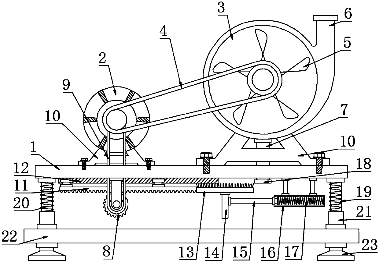
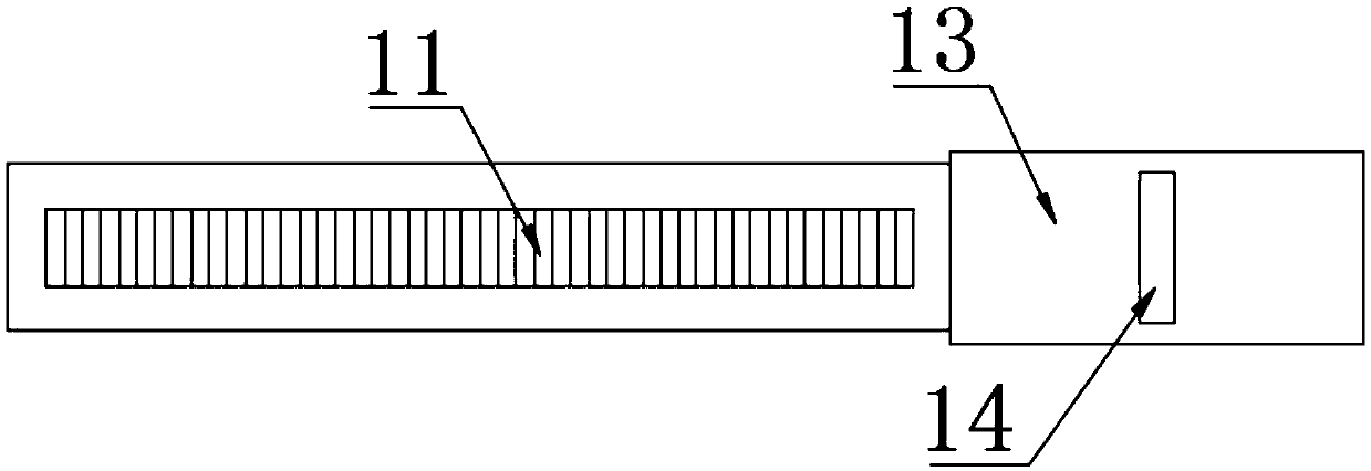
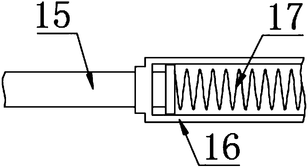
[0021] see Figure 1~4 , in an embodiment of the present invention, a ventilation device for industrial furnaces with anti-blocking function, including a mounting plate 1, a drive motor 2, an impeller 3, a tooth plate 11 and a brush plate 13; the two sides above the mounting plate 1 The driving motor 2 and the impeller 3 are respectively arranged, the lower parts of the driving motor 2 and the impeller 3 are fixedly connected to the supporting frame 10, the supporting frame 10 is fixedly connected to the mounting plate 1 by bolts, and the driving motor 2 leads are connected to the power supply and the switch, and pressing the switch makes The driving motor 2 is energized to drive the output end of the motor to rotate; the impeller 3 is internally connected to a blade 5 which is fixedly connected to the rotating shaft, and the rotating shaft is connected to the output end of the driving motor 2 through the first synchronous belt 4, and the side wall above the impeller 3 An air ...

Embodiment 2

[0024] In order to make the technical solution of this application more complete and detailed, some supplements and explanations are made on the basis of the above-mentioned embodiment 1, so that the technical means adopted in this application are disclosed more fully. Specifically, the technical characteristics of the added part are as follows: The two sides of the lower end of the mounting plate 1 are respectively fixedly connected with movable rods 19, the surface of the movable rod 19 is covered with a damping spring 20, and the lower part of the movable rod 19 is movably connected with the sleeve 21, and the lower end of the damping spring 20 abuts against the sleeve 21 , the lower end of the sleeve 21 is fixedly connected to the base plate 22, and the lower end of the base plate 22 is fixedly connected with a leg 23, and the mounting plate 1 is damped by the movable rod 19, the damping spring 20 and the sleeve 21 so as to achieve the damping effect on the impeller 3 , to ...


PUM


Abstract

The invention discloses ventilation equipment with an anti-blocking function for an industrial furnace. The ventilation equipment comprises a mounting plate, a driving motor, a turbine, a toothed plate and a brush plate, wherein the driving motor and the turbine are arranged on the two sides of the upper portion of the mounting plate correspondingly, each of the lower portion of the driving motorand the lower portion of the turbine is fixedly connected with a supporting frame, and the supporting frames are fixedly connected with the mounting plate through bolts; blades are rotationally connected in the turbine, an air inlet pipe is arranged at the bottom of the turbine, and a steel wire filter screen is fixedly connected to the lower end opening of the air inlet pipe; and an incomplete gear is arranged below the driving motor, the incomplete gear is connected with an output end of the driving motor through a second synchronous belt, the part provided with teeth of the incomplete gearis meshed the toothed plate, the right end of the toothed plate is fixedly connected with the brush plate, the lower portion of the brush plate is fixedly connected with a fixing plate, the fixing plate abuts against a telescopic rod, the telescopic rod is in sleeve fit with a sleeve, the sleeve is fixedly connected with the lower surface of the mounting plate, a returning spring is arranged in the sleeve, and the left end of the returning spring abuts against the right end of the telescopic rod.

Description

technical field [0001] The invention relates to a ventilator, in particular to a ventilator for an industrial kiln with an anti-blocking function. Background technique [0002] The fan is a machine that relies on the input mechanical energy to increase the gas pressure and discharge the gas. It is a driven fluid machine and is mainly used in various fields of the national economy such as metallurgy, petrochemical, electric power, urban rail transit, textiles, and ships. Ventilation of the place. In addition to traditional application fields, there will still be great development prospects in more than 20 potential market fields such as comprehensive utilization of coal gangue, technical transformation of new dry process clinker, energy saving in metallurgical industry, and comprehensive utilization of resources. [0003] Most of the existing kiln ventilation equipment uses a simple fan to perform air extraction and air supply functions, but a large amount of smoke and dust ...

Claims


Application Information

Patent Timeline
Patent Type & Authority Applications(China)
IPC IPC(8): F04D25/08F04D29/66F04D29/70
CPCF04D25/08F04D29/668F04D29/703
Inventor 贾雄峰裴宝地刘宏波王浩马红霞
Owner ROYAL POWER WUHAN CO LTD
Features
  • R&D
  • Intellectual Property
  • Life Sciences
  • Materials
  • Tech Scout
  • Unparalleled Data Quality
  • Higher Quality Content
  • 60% Fewer Hallucinations
Learn More