Full-bridge pilot control switch valve
A pilot-controlled, full-bridge technology, applied in valve details, valve device, valve operation/release device, etc., can solve problems such as inability to overcome the hydraulic force to push the valve core, increase the size of the on-off valve, and increase the complexity, etc. Achieve the effect of improving the ability to resist external disturbance, reducing the size and control power
- Summary
- Abstract
- Description
- Claims
- Application Information
AI Technical Summary
Problems solved by technology
Method used
Image
Examples
Embodiment 1
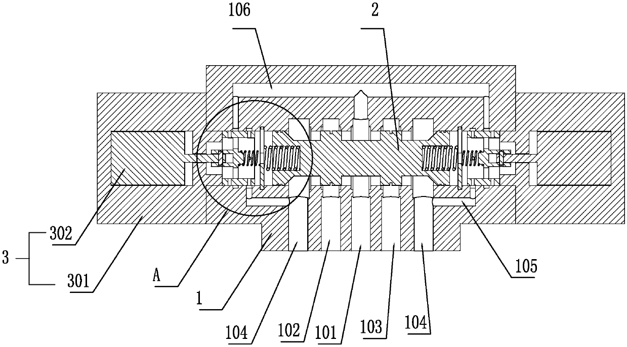
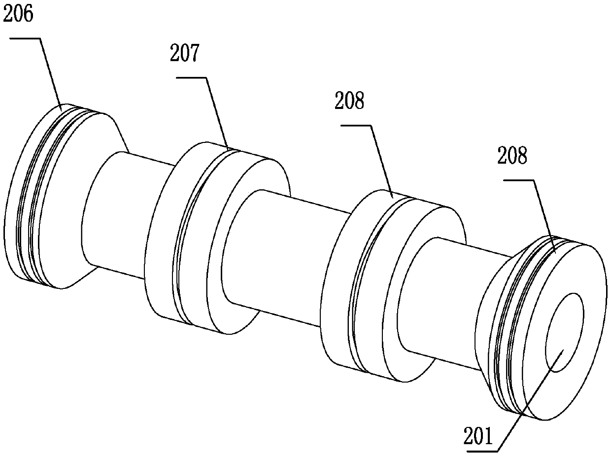
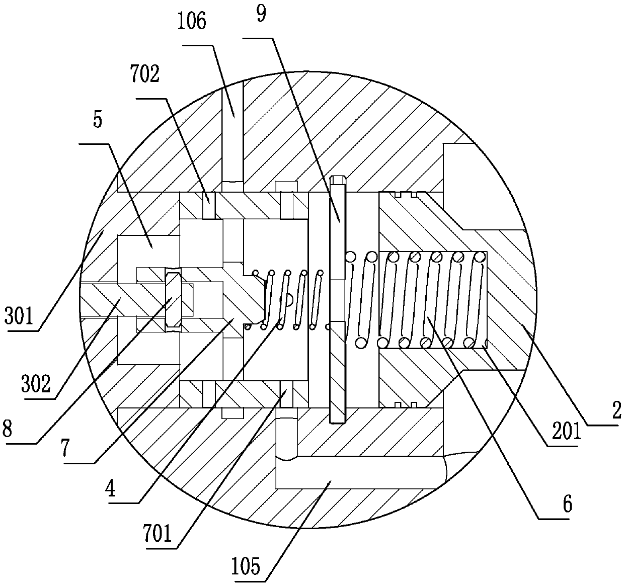
[0032] Such as figure 1 As shown, a full-bridge pilot control switching valve includes a valve body 1 and a main valve core 2. The valve body 1 is provided with a high-pressure oil inlet 101, a first control oil port 102, and a second control oil port 103. , Two low-pressure oil outlets 104 (can be 0 pressure), two low-pressure oil outlets 104 are arranged on both sides, high-pressure oil inlet 101 is arranged in the middle, the first control oil port 102, the second control oil port 103 respectively Set between the two low-pressure oil outlets 104 and the high-pressure oil inlet 101, such as figure 2As shown, the main valve core 2 is provided with a first protruding ring 206, a second protruding ring 207, a third protruding ring 208, and a fourth protruding ring 209 in the circumferential direction, and the first protruding ring 206 and the fourth protruding ring 209 are respectively located at The two ends of the main spool 2 are in dynamic sealing cooperation with the val...
Embodiment 2
[0044] Such as Figure 5 As shown, a full-bridge pilot control on-off valve includes a valve body 1 and a main valve core 2. The valve body 1 is provided with a high-pressure oil inlet 101, a first control oil port 102, and a second control oil port 103. , Two low-pressure oil outlets 104 (can be 0 pressure), two low-pressure oil outlets 104 are arranged on both sides, high-pressure oil inlet 101 is arranged in the middle, the first control oil port 102, the second control oil port 103 respectively Set between the two low-pressure oil outlets 104 and the high-pressure oil inlet 101, the main valve core 2 is provided with a first protruding ring 206, a second protruding ring 207, a third protruding ring 208, and a fourth protruding ring 209 in the circumferential direction. The first protruding ring 206 and the fourth protruding ring 209 are respectively located at both ends of the main valve core 2 and are in dynamic sealing cooperation with the valve body 1 (the seal can be i...
PUM
 Abstract
Description
Claims
Application Information
 - R&D
- Intellectual Property
- Life Sciences
- Materials
- Tech Scout
- Unparalleled Data Quality
- Higher Quality Content
- 60% Fewer Hallucinations
Browse by: Latest US Patents, China's latest patents, Technical Efficacy Thesaurus, Application Domain, Technology Topic, Popular Technical Reports.
© 2025 PatSnap. All rights reserved.Legal|Privacy policy|Modern Slavery Act Transparency Statement|Sitemap|About US| Contact US: help@patsnap.com


