Electric appliance heating device

A technology for heating devices and electrical appliances, which is applied to electric heating fuel, heating methods, lighting and heating equipment, etc., and can solve the problems of non-reusable use and waste of heat energy, etc.

Inactive Publication Date: 2019-04-05
张梦娟
View PDF0 Cites 1 Cited by
  • Summary
  • Abstract
  • Description
  • Claims
  • Application Information

AI Technical Summary

Problems solved by technology

As attached to the manual Figure 1~3 The shape and structure of the common electrical heating device are shown in the figure (the arrow in the figure is the direction of wind flow), generally speaking, the air outlet of the electrical heating device often has Figure 1~3 Among the three methods, the above-mentioned air outlets have the following disadvantages: the air from the air outlets is directly emitted to the outside, which cannot be reused and wastes heat energy

Method used


Image

  • Electric appliance heating device
  • Electric appliance heating device
  • Electric appliance heating device

Examples


Embodiment Construction

[0019] The present invention will be described in further detail below in conjunction with the accompanying drawings and specific embodiments.

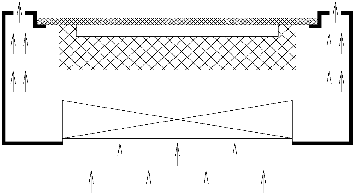
[0020] Such as Figure 4 ~ Figure 9 As shown, an electrical heating device includes an outer casing 1 with an inner cavity and a heating element 2, and the cross section of the outer casing 1 is preferably circular.

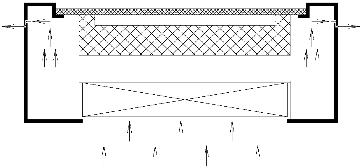
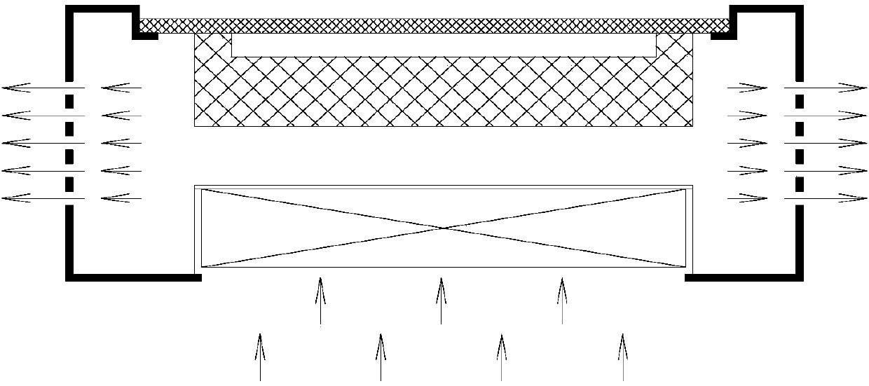
[0021] The outer casing 1 is provided with an air inlet 11 which communicates with the inner cavity. Air outlet 12 , the air outlet 12 is used to discharge air, and the flow direction of the air discharged from the air outlet 12 faces the side close to the outer casing 1 .

[0022] A fan 6 is installed at the air inlet 11, and the fan 6 can be fixed in the inner cavity of the outer shell 1 by welding or screwing, for example: the fan 6 is formed with a threaded through hole, and the fan 6 can be connected by the threaded through hole and the screw. The fan 6 is fixed on the outer casing 1 .

[0023] Such as Figure 7...


PUM


Abstract

The invention discloses an electric appliance heating device. The electric appliance heating device comprises an outer shell with an inner cavity. The upper end of the outer shell is provided with anair outlet communicating with the inner cavity. The air outlet is used for exhausting air in the inner cavity. The air exhausted from the air outlet flows towards the side close to the outer shell, and is used for heating an outer furnace body. In the electric appliance heating device, part of heat in the inner cavity of the electric appliance heating device can be exhausted through the air outlet, and damage due to overheat of the inner cavity can be prevented. Since the air exhausted from the air outlet of the electric appliance heating device flows towards the side close to the outer shell,the air (with heat) exhausted from the air outlet can heat the furnace body (the furnace body is an outer container) placed above a heating body again. The air outlet arranged in the electric appliance heating device can have the function of heat dissipation and mainly assists in inner cavity heat dissipation, air exhausted from the air outlet can heat the furnace body again, and two purposes areachieved through one action.

Description

technical field [0001] The invention relates to an electric heating device. Background technique [0002] The electric heating device is a kind of stove equipment that converts electric energy into heat energy by using the thermal effect of electric current. Its main structure is composed of a heating plate and a furnace body. As attached to the manual Figure 1~3 The shape and structure of the common electrical heating device are shown in the figure (the arrow in the figure is the direction of wind flow), generally speaking, the air outlet of the electrical heating device often has Figure 1~3 Among the three methods, the above-mentioned air outlets all have the following disadvantages: the wind from the air outlets is directly distributed to the outside, which cannot be reused and wastes heat energy. Contents of the invention [0003] The invention discloses an electric heating device to solve at least one aspect of the above-mentioned technical problems. [0004] Accor...

Claims


Application Information

Patent Timeline
Patent Type & Authority Applications(China)
IPC IPC(8): F24C7/06F24C15/34
CPCF24C7/06F24C15/34
Inventor 张梦娟
Owner 张梦娟
Why Eureka
Try Eureka