Line sag online detection system and method based on differential locating

A differential positioning and detection system technology, applied in radio wave measurement systems, satellite radio beacon positioning systems, measurement devices, etc., can solve the problems of complex detection process and inability to identify the sag height of transmission lines, etc., and achieve the effect of simple installation

Pending Publication Date: 2019-04-05
上海申贝科技发展有限公司
View PDF6 Cites 8 Cited by
  • Summary
  • Abstract
  • Description
  • Claims
  • Application Information

AI Technical Summary

Problems solved by technology

However, limited by image recognition technology, it can only recognize the sag height with simple environment and clear target, but cannot recognize the sag height of transmission lines in complex environment, and the detection process is complicated

Method used


Image

  • Line sag online detection system and method based on differential locating
  • Line sag online detection system and method based on differential locating
  • Line sag online detection system and method based on differential locating

Examples


Embodiment 1

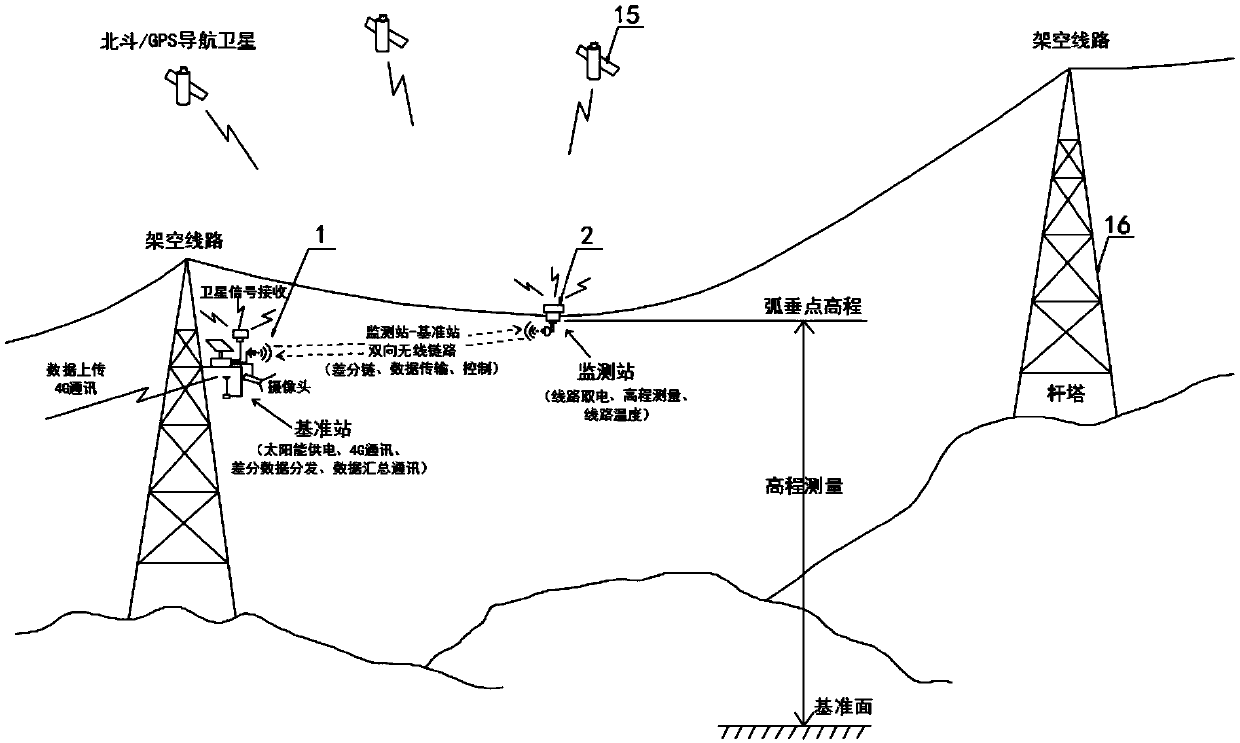
[0031] according to figure 1 A line sag online detection system based on differential positioning is shown, including a reference station 1 and a monitoring station 2, and the reference station 1 is fixedly equipped with a solar power supply system 3, a first satellite receiving module 4, and a first CPU processing device 5, the first wireless data transmission station 6, 4G communication module 7 and field expansion communication interface 8, and the monitoring station 2 is fixedly equipped with a second satellite receiving module 9, a second CPU processor 10, a second wireless data transmission Radio station 11, attitude and movement measuring unit 12, non-contact infrared temperature measuring sensor 13 and line power taking module 14, described first satellite receiving module 4 and second satellite receiving module 9 are connected with Beidou / GPS navigation satellite 15 signals, The reference station 1 and the monitoring station 2 are wirelessly connected through the firs...

Embodiment 2

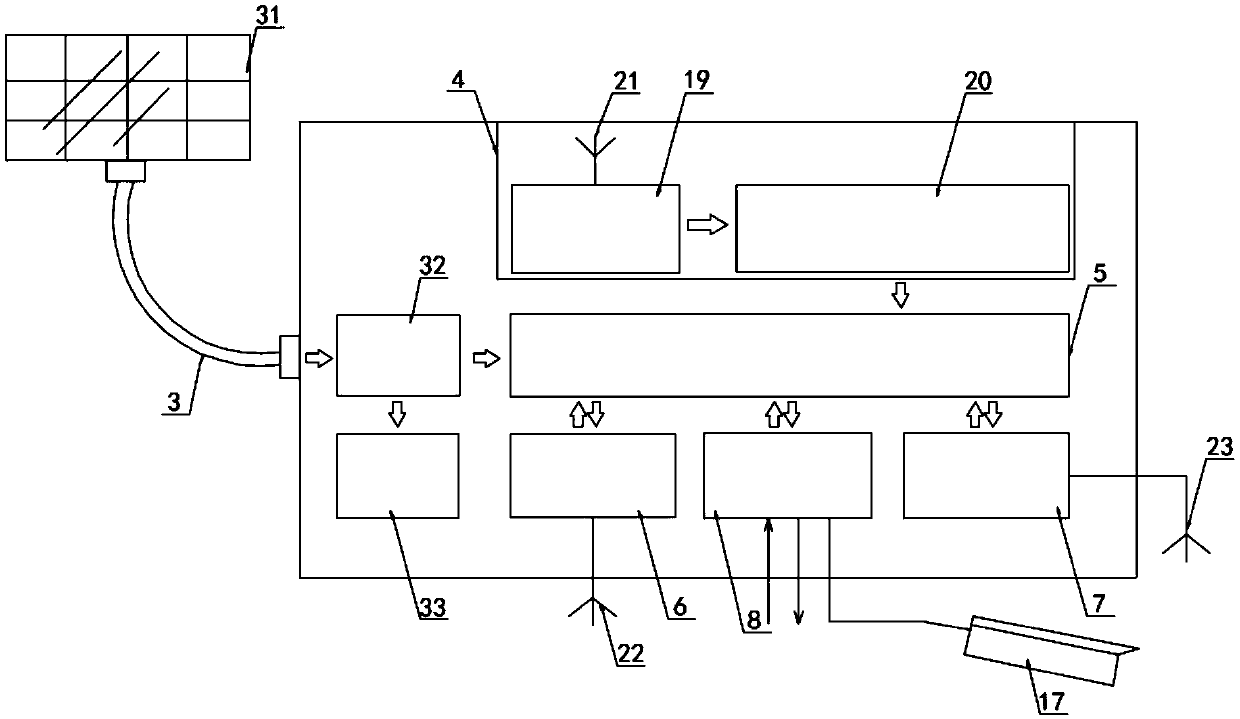
[0036] according to figure 2 As shown, a line sag online detection system based on differential positioning, the solar power supply system 3 includes a solar panel 31, a solar controller 32 and a battery pack 33, the solar controller 32 is electrically connected to the solar panel 31, The battery pack 33 is electrically connected to the solar controller 32, and the battery pack 33 is connected to the reference station 1 through wires;

[0037] The output end of the first satellite receiving module 4 is connected to the input end of the first CPU processor 5, and the first wireless data transmission station 6, the field expansion communication interface 8 and the 4G communication module 7 are all connected to the first CPU processor 5 , the 4G communication module 7 is externally connected to a 4G antenna 23;

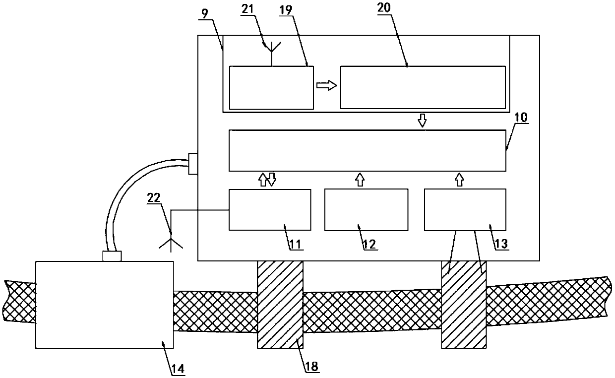
[0038] according to image 3 A line sag online detection system based on differential positioning is shown, the output end of the second satellite receiving module 9 ...


PUM


Abstract

The invention discloses a line sag online detection system based on differential locating. The line sag online detection system comprises a base station and a monitoring station; the base station is fixedly provided with a solar energy power supply system, a first satellite receiving module, a first CPU, a first wireless data radio, a 4G communication module and a site extended communication interface; and the monitoring station is fixedly provided with a second satellite receiving module, a second CPU, a second wireless data radio, a pose and motion measuring unit, a non-contact infrared temperature measurement sensor and a line electricity taking module. According to the line sag online detection system based on the differential locating, the base station is arranged on a tower or otherreliable fixed positions, the monitoring station is installed at a line sag point, a satellite differential locating technology is adopted, the base station and the monitoring station receive satellite signals at the same time, real-time differential resolving is carried out through wireless differential links, the elevation and horizontal positions of monitoring points are measured, and the real-time monitoring of the line sag is realized through the combination of data such as line temperature measurement and pose and motion measurement.

Description

technical field [0001] The invention relates to the technical field of line sag detection, in particular to an online line sag detection system and detection method based on differential positioning. Background technique [0002] In the transmission line, if the sag height of the conductor exceeds a certain range, the conductor will discharge due to insufficient crossing distance, endangering the power production and the safety around the transmission line. Therefore, the sag height of the conductor must be limited within a certain threshold range. To ensure the safe and stable operation of transmission lines. [0003] Traditional sag monitoring methods include different length method, angle method, gear end observation method, etc. These methods need to send inspection personnel to the site for measurement, and their accuracy is greatly affected by angle measurement and visual estimation readings, and the measurement process is cumbersome. And the cycle is long and the cos...

Claims


Application Information

Patent Timeline
IPC IPC(8): G01S19/14G01S19/41
CPCG01S19/14G01S19/41
Inventor 李鸥王峭峻邓晓航黄凯沈星夏陈定坤
Owner 上海申贝科技发展有限公司
Why Eureka
Try Eureka