Intelligent optical distribution frame

A technology of optical fiber intelligence and distribution frame, which is applied in the direction of light guide, optics, optical components, etc., can solve the problems of single function, small pigtail storage capacity, inconvenient deployment and connection operation, etc., and achieve simple and compact structure, space saving, and easy operation Effect

Active Publication Date: 2019-04-05
STATE GRID TIANJIN ELECTRIC POWER +1
View PDF8 Cites 3 Cited by
  • Summary
  • Abstract
  • Description
  • Claims
  • Application Information

AI Technical Summary

Problems solved by technology

[0004] The business of the power communication system is relatively flexible, and there are often business cutovers, optical path detours, changes, and withdrawals that require optical path jumper adjustments. Currently, the optical fiber distribution frames used for optical fibers are relatively fixed, and it is difficult to change and remove jumpers. Encountering adverse effects on the business of the optical path in operation; at the same time, it has the disadvantages of small pigtail storage capacity, inconvenient deployment and connection operation, and single function.

Method used


Image

  • Intelligent optical distribution frame
  • Intelligent optical distribution frame
  • Intelligent optical distribution frame

Examples


Embodiment 1

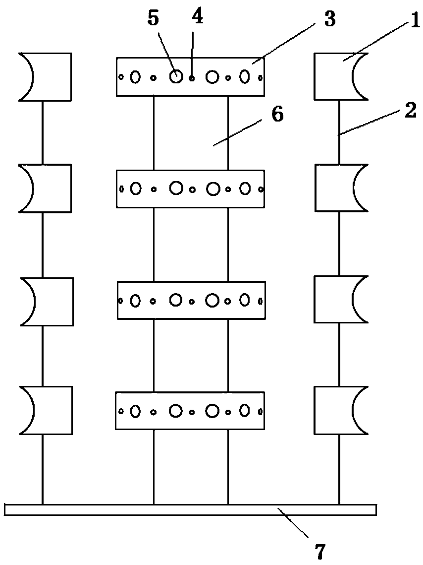
[0029] An optical fiber intelligent distribution frame of the present invention comprises a horizontally arranged bottom plate 7, a hollow cylindrical frame 6 vertically arranged on the bottom plate 7, and four wiring rings sleeved on the cylindrical frame 6 at intervals 3 and the fiber coil frame 1 for coiling optical fibers arranged on the periphery of the junction ring 3; the cylindrical frame 6 is used to pass through the optical fiber when in use; 24 optical fibers are penetrated on the ring wall of the junction ring 3 Flange head 5, these 24 fiber optic flange heads 5 are evenly spaced, and the inner end of described fiber optic flange head 5 (the end near cylindrical frame 6) communicates with the inside of described cylindrical frame 6, so that from cylindrical frame 6 The passing optical fiber can pass through the fiber optic flange head 5 smoothly; a monitoring assembly for monitoring the real-time status of the optical fiber is arranged in the junction ring 3, and a ...

Embodiment 2

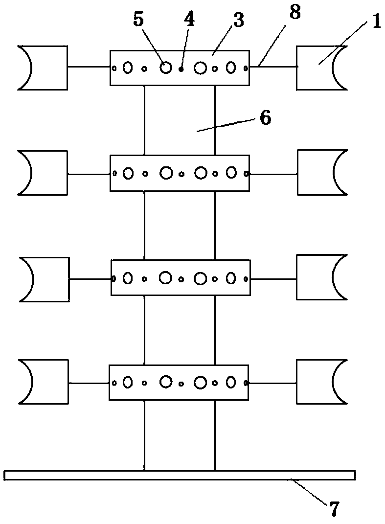
[0033] An optical fiber intelligent distribution frame of the present invention comprises a horizontally arranged bottom plate 7, a hollow cylindrical frame 6 vertically arranged on the bottom plate 7, and four wiring rings sleeved on the cylindrical frame 6 at intervals 3 and the coil frame 1 for coiling the optical fiber arranged on the periphery of the junction ring 3; the cylindrical frame 6 is used to pass the optical fiber during use; the ring wall of the junction ring 3 is provided with 48 optical fibers Flange head 5, these 48 fiber optic flange heads 5 are evenly spaced, and the inner end of described fiber optic flange head 5 (the end near cylindrical frame 6) communicates with the inside of described cylindrical frame 6, so that from cylindrical frame 6 The passing optical fiber can pass through the fiber optic flange head 5 smoothly; a monitoring assembly for monitoring the real-time status of the optical fiber is arranged in the junction ring 3, and a warning light...

Embodiment 3

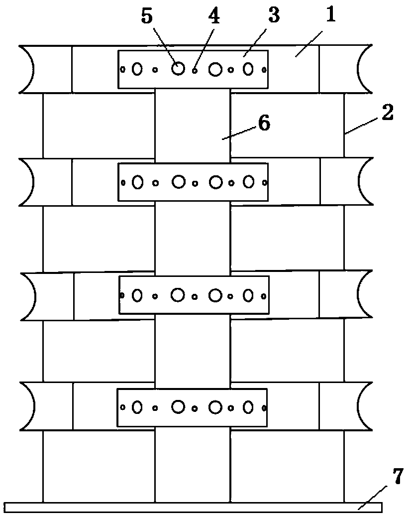
[0037]An optical fiber intelligent distribution frame of the present invention comprises a horizontally arranged bottom plate 7, a hollow cylindrical frame 6 vertically arranged on the bottom plate 7, and four wiring rings sleeved on the cylindrical frame 6 at intervals 3 and the coil frame 1 for coiling optical fibers arranged on the periphery of the junction ring 3; the cylindrical frame 6 is used to pass through the optical fibers during use; 72 optical fibers are penetrated on the ring wall of the junction ring 3 Flange head 5, these 72 fiber optic flange heads 5 are evenly spaced, and the inner end of described fiber optic flange head 5 (the end near cylindrical frame 6) communicates with the inside of described cylindrical frame 6, so that from cylindrical frame 6 The passing optical fiber can pass through the fiber optic flange head 5 smoothly; a monitoring assembly for monitoring the real-time status of the optical fiber is arranged in the junction ring 3, and a warning...


PUM


Abstract

The invention discloses an intelligent optical distribution frame comprising a base plate, a hollow cylindrical frame vertically arranged on the base plate, wiring rings sleeved on the cylindrical frame at intervals, and cable winding racks arranged at the peripheries of the wiring rings and used for winding optical fibers; an optical fiber flange head is arranged on the annular wall of each wiring ring in a penetrating manner; the inner end of each optical fiber flange head is communicated with the interior of the cylindrical frame; a monitoring component used for monitoring the real-time state of the optical fiber is arranged in the wiring ring; and an alarm light is arranged on the outer wall of the wiring ring. The intelligent optical distribution frame provided by the invention is compact in structure and saving in space; due to the wiring rings arranged at intervals and the cable winding racks arranged at the peripheries of the wiring rings, the more optical fibers can be accommodated, and meanwhile the optical fibers can be orderly wound on the cable winding racks, and the adverse effects on the business caused by mistakenly touching the light path in running are avoided; furthermore, the running state of the light path channel can be better monitored in real time.

Description

technical field [0001] The invention belongs to the technical field of electric power communication equipment, and relates to an auxiliary equipment in an optical fiber transmission system, in particular to an optical fiber intelligent distribution frame. Background technique [0002] Optical distribution frame ODF (Optical Distribution Frame) is an important supporting equipment in the optical fiber transmission system. The connection, distribution and scheduling of optical fiber lines have the functions of fixing and protecting optical cables, terminating optical cables and adjusting lines, which play an important role in the safe operation and flexible use of optical fiber communication networks. [0003] According to different structures, optical fiber distribution frames can be divided into wall-mounted and rack-mounted. The wall-mounted optical fiber distribution frame can be directly fixed on the wall, and is generally a box structure, which is suitable for places wi...

Claims


Application Information

Patent Timeline
Patent Type & Authority Applications(China)
IPC IPC(8): G02B6/44
CPCG02B6/4452G02B6/4469
Inventor 张倩宜崔朋家王梓蒴李妍孟兆娜郑庆竹胡博常晓润蔺涛高建斌
Owner STATE GRID TIANJIN ELECTRIC POWER
Why Eureka
Try Eureka