

Lens and terminal equipment
A technology of terminal equipment and lens, which is applied in the field of lens, can solve the problem of poor depth recognition accuracy of the lens, and achieve the effect of meeting the requirements of depth recognition accuracy, large aperture, and improving depth recognition accuracy
- Summary
- Abstract
- Description
- Claims
- Application Information
AI Technical Summary
Problems solved by technology
Method used
Image

Examples
specific Embodiment 1
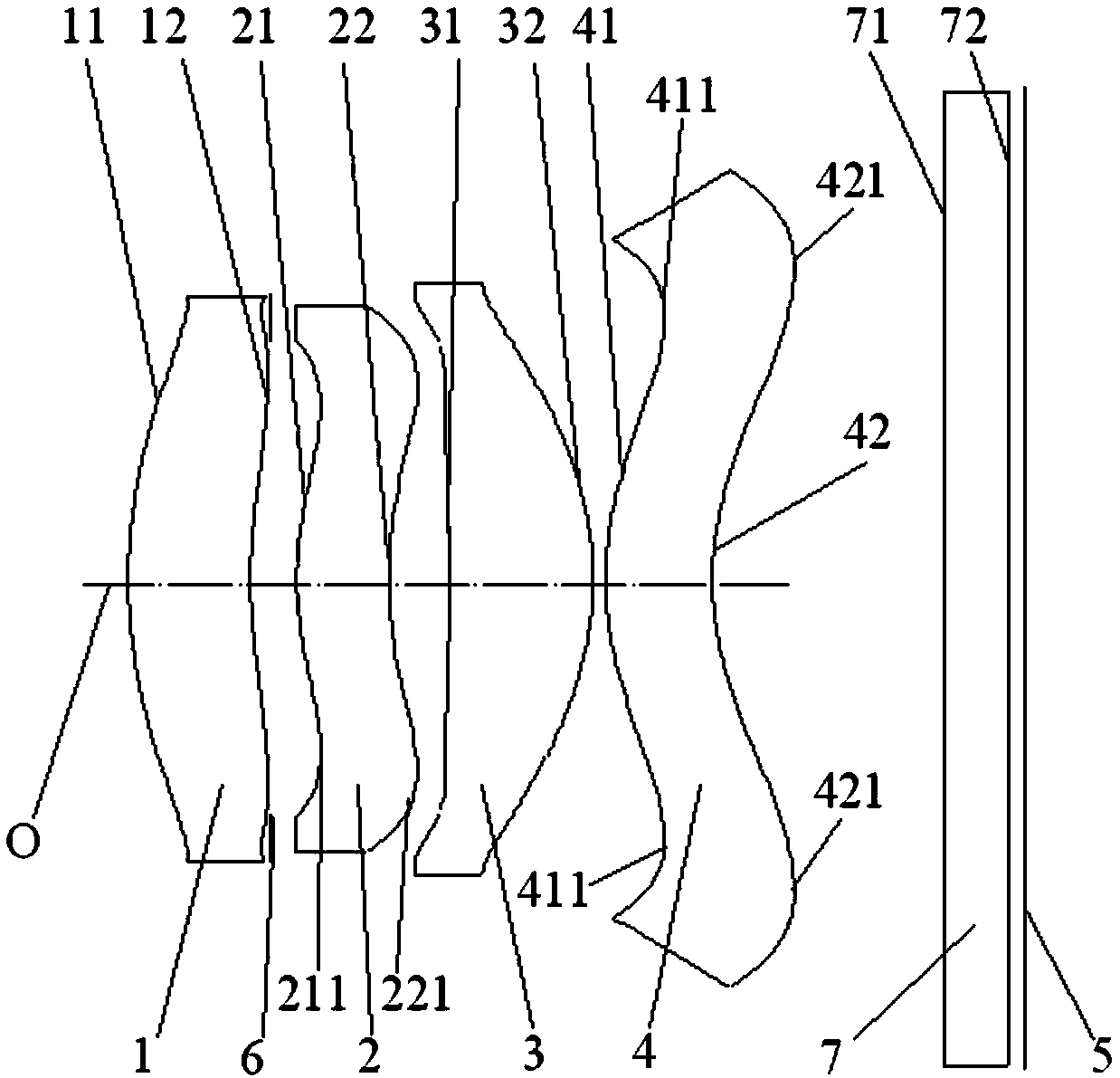
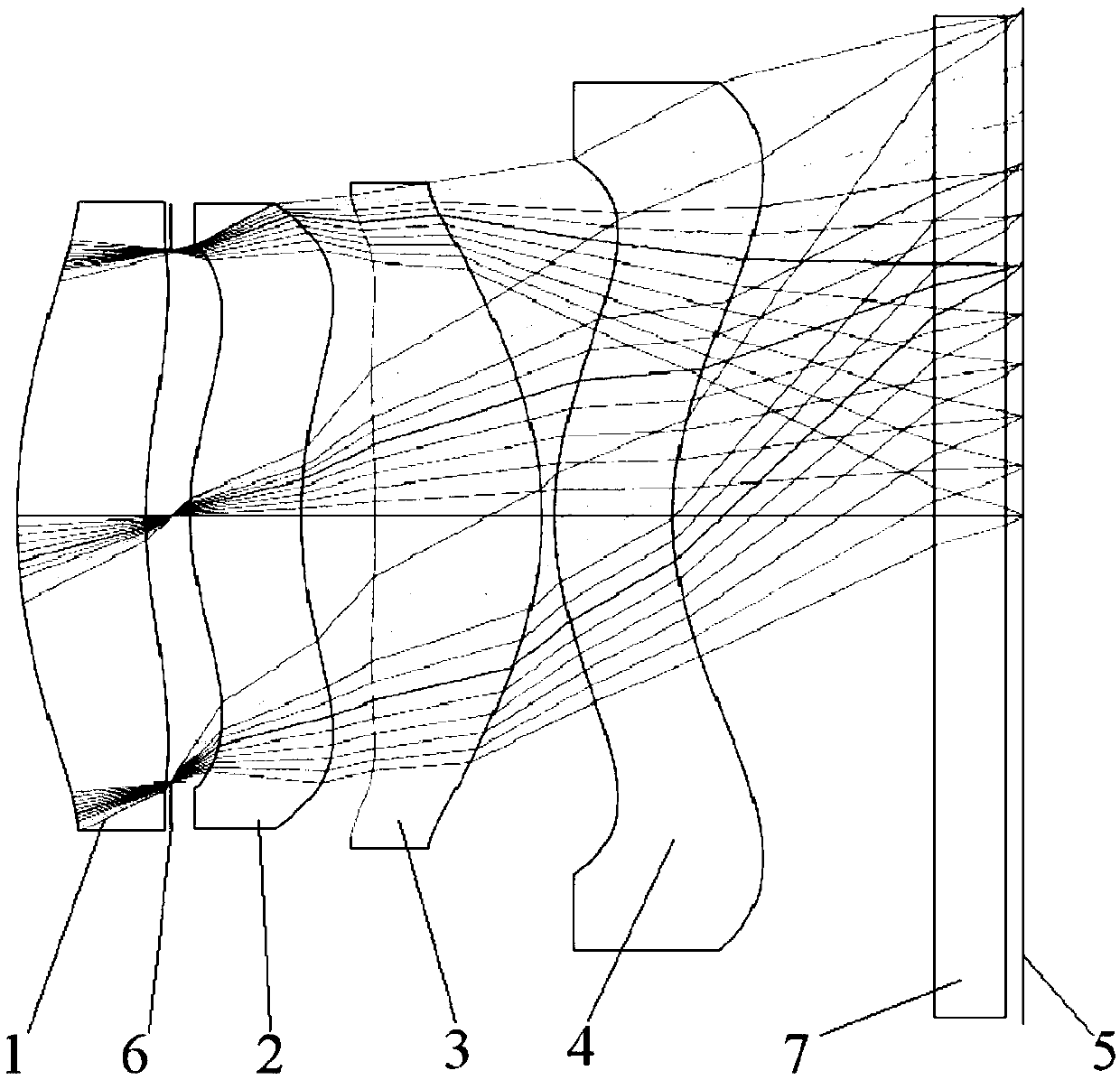
[0079] figure 1 Shown is a schematic view of the lens structure of the specific embodiment one, such as figure 1As shown, the lens includes a first lens 1, a second lens 2, a third lens 3 and a fourth lens 4 arranged in sequence along the main optical axis O from the measured object to the imaging surface 5, the first lens 1 and the second lens An aperture stop can be set between the two lenses 2, and the specific parameters of each lens are provided in Table 1, and the conic coefficient k and aspheric coefficient Ai (i=4, 6, 8, 10) of each lens surface are provided in Table 2. , 12, 14, 16, 18, 20).
[0080]
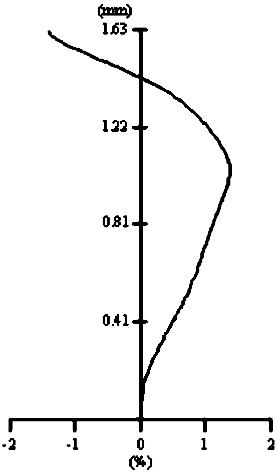
[0081] It can be seen from Table 1 that |f / f1|+|f / f2|=0.43, f / (2*Imh)=0.61, (L3R1+L3R2) / (L3R1-L3R2)=1.92, L4R1 / f=1 / 1.83 , RI / cos 4 (HFOV) = 1.27. Therefore, the lens of the specific embodiment 1 satisfies the limited range of the parameters of the lens group in the present application, and the lens group of the specific embodiment 1 can take into account the requ...
specific Embodiment 2
[0087] Figure 6 Shown is the lens structure of specific embodiment two, as Figure 6 As shown, the lens includes a first lens 1, a second lens 2, a third lens 3 and a fourth lens 4 arranged in sequence along the main optical axis O from the measured object to the imaging surface 5. Table 3 shows For the specific parameters of each lens, Table 4 gives the conic coefficient k and aspheric coefficient Ai (i=4, 6, 8, 10, 12, 14, 16, 18, 20) of each lens surface.
[0088]
[0089] It can be seen from Table 3 that |f / f1|+|f / f2|=0.32, f / (2*Imh)=0.6, (L3R1+L3R2) / (L3R1-L3R2)=1.74, L4R1 / f=1 / 1.81 , RI / cos 4 (HFOV) = 1.4. Therefore, the lens of the specific embodiment 2 satisfies the limited scope of the parameters of the lens group in the present application, and the lens group of the specific embodiment 2 can take into account the requirements of the TOF system on the lens illuminance and aperture value under the premise of ensuring the miniaturization of the lens, thereby Meet ...
specific Embodiment 3
[0096] Figure 10 Shown is the lens structure of specific embodiment three, as Figure 10 As shown, the lens includes a first lens 1, a second lens 2, a third lens 3 and a fourth lens 4 arranged in sequence along the main optical axis O from the measured object to the imaging surface 5. Table 5 shows For the specific parameters of each lens, Table 6 shows the conic coefficient k and aspheric coefficient Ai (i=4, 6, 8, 10, 12, 14, 16, 18, 20) of each lens surface.
[0097]
[0098] It can be seen from Table 5 that |f / f1|+|f / f2|=0.4, f / (2*Imh)=0.6, (L3R1+L3R2) / (L3R1-L3R2)=2.15, L4R1 / f=1 / 1.81 , RI / cos 4 (HFOV) = 1.26. Therefore, the lens of the specific embodiment three satisfies the limited scope of the parameters of the lens group in the present application, and the lens group of the specific embodiment three can take into account the requirements of the TOF system on the lens illuminance and aperture value under the premise of ensuring the miniaturization of the lens, th...
PUM
 Abstract
Description
Claims
Application Information