Power cable protection sleeve pipe with waterproof structure

A technology for power cables and waterproof structures, applied in electrical components and other directions, can solve problems such as inability to effectively fix cables, unstable structure, poor heat dissipation, etc., and achieve the effects of convenient installation, ensuring stability and reducing volume

Active Publication Date: 2019-04-05
河北鑫鹏通信设备有限公司
View PDF6 Cites 1 Cited by
  • Summary
  • Abstract
  • Description
  • Claims
  • Application Information

AI Technical Summary

Problems solved by technology

However, the current cable protection tube cannot effectively fix the cable, it is easy to enter water, the structure is unstable, it is easy to shake, and the heat dissipation is not good

Method used


Image

  • Power cable protection sleeve pipe with waterproof structure
  • Power cable protection sleeve pipe with waterproof structure
  • Power cable protection sleeve pipe with waterproof structure

Examples


Embodiment 1

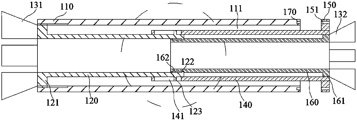
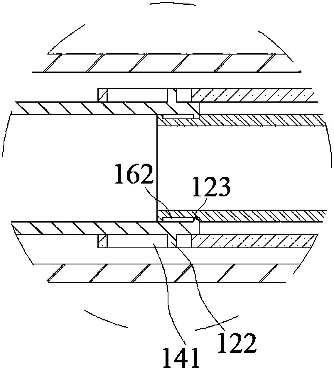
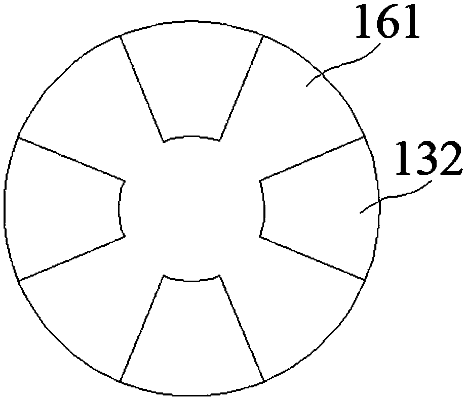
[0105] Such as figure 1 , figure 2 with image 3 As shown, this embodiment provides an electrical line protection tube with a clamping structure, which includes a tube body 110, a lumen 111 is provided in the tube body 110, and a first movable tube 120 is provided in the lumen 111. The left end of the movable tube 120 is provided with a first convex ring 121, which is threadedly connected to the cavity wall of the lumen 111; the inner and outer sides of the right end of the first movable tube 120 are respectively sleeved with a third movable tube 160 and The second movable tube 140 and the third movable tube 160 are located in the inner cavity of the second movable tube 140; the right end of the second movable tube 140 is provided with a baffle ring 150, and the right end of the third movable tube 160 is provided with a second convex ring 161. The ring 161 abuts on the inner wall of the right end of the second movable tube 140; the left side of the first convex ring 121 is prov...

Embodiment 2

[0126] Such as Figure 4 with Figure 5 As shown, this embodiment provides a protective device for electrical pipelines, which includes a tube body 110, a tube cavity 111 is provided in the tube body 110, a water inlet 210 is provided on the top of the tube body 110, and the top of the tube cavity 111 is A first water collection tank 220 is provided. The first water collection tank 220 is provided with a first water collection cavity 221. The first water collection cavity 221 communicates with the water inlet 210; the bottom of the cavity 111 is provided with a second water collection tank 230 A second water collection cavity 231 is provided in the second water collection tank 230, and the second water collection cavity 231 and the first water collection cavity 221 are in communication with each other through a plurality of connecting pipes 240.

[0127] The water inlet 210 on the top of the pipe body 110 can easily collect the water above the pipe body 110 into the first water co...

Embodiment 3

[0141] Such as Figure 8 with Picture 9 As shown, this embodiment provides a wall-piercing device for power cables with better stability, which includes a tube body 110, a tube cavity 111 is provided in the tube body 110, and a fixing tube 310 is threaded on the outer side of the tube body 110. , The outer side of the fixed pipe 310 is threaded with more than two collars 320, the outer side of the fixed pipe 310 and the collar 320 are set in the cement layer of the wall through hole; the outside of the pipe body 110 is also threaded with two rings 330. The two circular rings 330 are located at both ends of the fixed tube 310, and the inner side of the circular ring 330 is provided with a containing cavity 331, and the cavity wall of the containing cavity 331 can be threaded on the outside of the fixed tube 310.

[0142] The threaded socket connection between the pipe body 110 and the fixed pipe 310 enables the pipe body 110 to be detached from the fixed pipe 310. When the fixed p...


PUM


Abstract

The invention relates to the technical field of electrical pipes and relates to a power cable protection sleeve pipe with a waterproof structure. A pipe body is provided with a pipe cavity, the pipe cavity is provided with a first movable pipe, the first movable pipe is provided with a first convex ring which is threadingly connected to the pipe cavity. A third movable tube is sleeved in the rightend of the first movable tube in a left-and-right stretching way, a second movable tube is sleeved outside the right end of the first movable tube in a left-and-right stretching way. The right end ofthe second movable tube is provided with a retaining ring, the third movable tube is provided with a second convex ring which abuts against the inner wall of the right end of the second movable tube.The first convex ring is provided with a first plug block, and the second convex ring is provided with a second plug block. The top of the pipe body is provided with a water inlet hole, the top of the pipe cavity is provided with a first water collecting tank which is internally provided with a first water collecting cavity, and the first water collecting cavity communicates with the water inlethole. The bottom in the pipe cavity is provided with a second water collecting tank which is internally provided with a second water collecting cavity, and the second water collecting cavity communicates with the first water collecting cavity through a connecting pipe. Two ports of the power cable protection sleeve pipe can be clamped for waterproofing, and water can be collected for heat dissipation.

Description

Technical field [0001] The invention relates to the technical field of electrical pipes, in particular to a power cable protective sleeve with a waterproof structure. Background technique [0002] Electrical pipelines are generally put into protection pipes during installation, so that the protection pipes protect the electrical pipelines. The protective tube is generally used to protect the cable. The cable protective tube refers to a protective tube with a certain mechanical strength that is laid on the outer layer of the cable to prevent the cable from being damaged. The cable protection tube is mainly installed at the intersection of the communication cable and the power line to prevent the power line from breaking and causing a short circuit accident, causing the communication cable and steel wire rope to become live, so as to protect the cable, switch, and core board, and even the whole machine will not be burned out. Magnetic field interference also plays a role in isolat...

Claims


Application Information

Patent Timeline
IPC IPC(8): H02G3/04H02G3/22
CPCH02G3/0406H02G3/0412H02G3/0481H02G3/22
Inventor 谢长山
Owner 河北鑫鹏通信设备有限公司
Why Eureka
Try Eureka