Piezoelectric microphone

A microphone and piezoelectric technology, applied in the field of acoustic-electrical conversion, can solve the problems affecting the performance of the microphone and the deformation of the diaphragm of the diaphragm, and achieve the effect of reducing the performance difference, improving the uniformity and improving the consistency.

Active Publication Date: 2019-04-05
AAC ACOUSTIC TECH (SHENZHEN) CO LTD
View PDF9 Cites 15 Cited by
  • Summary
  • Abstract
  • Description
  • Claims
  • Application Information

AI Technical Summary

Problems solved by technology

[0007] Aiming at the technical problem that the deformation of the flaps of the diaphragm of the piezoelectric microphone in the related art is different due to the influence of stress during the processing process, thereby affecting the performance of the microphone, the present invention provides a piezoelectric microphone with better performance. electric microphone

Method used


Image

  • Piezoelectric microphone
  • Piezoelectric microphone
  • Piezoelectric microphone

Examples


Embodiment 1

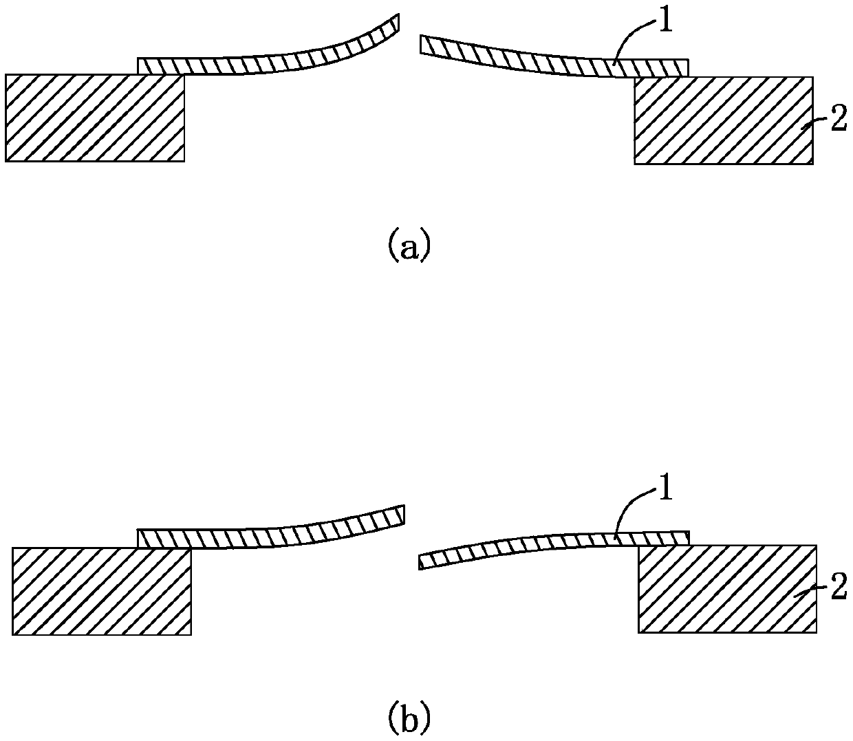
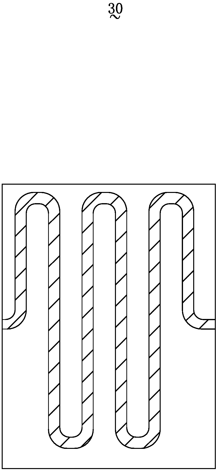
[0026] Please refer to figure 2 and image 3 . This embodiment provides a piezoelectric microphone 100, which includes a substrate 10 with a cavity back, a piezoelectric cantilever diaphragm 20 fixed on the substrate 10, and a piezoelectric cantilever diaphragm 20 fixed on the piezoelectric microphone 100. The elastic expansion part 30.

[0027] The piezoelectric cantilever beam diaphragm 20 includes a first diaphragm 21 located at the center and suspended above the back cavity, and a second diaphragm fixed on the base 10 and arranged around the first diaphragm 21 Film 22. The first vibrating membrane 21 and the second vibrating membrane 22 are deformed under the action of external sound pressure to sense the sound pressure signal. The second diaphragm 22 is composed of a plurality of diaphragms 221, and the diaphragm 221 includes a fixed end 2211 fixed on one side of the base 10 and a side close to the first diaphragm 21 and suspended on the Active end 2212 above the do...

Embodiment 2

[0038] Please refer to Figure 4 and Figure 5 . This embodiment provides a piezoelectric microphone 200, the structure of the piezoelectric microphone 200 is basically the same as that of the piezoelectric microphone 100 in Embodiment 1, the difference lies in:

[0039] The second diaphragm 122 of the piezoelectric cantilever diaphragm 120 of the piezoelectric microphone 200 is composed of four fan-shaped diaphragms 1221, and the first diaphragm 121 of the piezoelectric cantilever diaphragm 120 is circular. . The four flaps 1221 are symmetrically arranged in pairs to enclose a circular space, and the first diaphragm 121 is correspondingly located in the circular space and spaced apart from the flaps 1221 . The second diaphragm 122 and the first diaphragm 121 together form the piezoelectric cantilever diaphragm 120 having a circular structure.

[0040] At the same time, there are four elastic elastic members 130, and the four elastic elastic members 130 are all in the same...


PUM


Abstract

The invention provides a piezoelectric microphone, which comprises a base with a back cavity and a piezoelectric cantilever beam diaphragm fixed on the base, wherein the piezoelectric cantilever beamdiaphragm comprises a first diaphragm located in the center and suspended above the back cavity and a second diaphragm fixed on the base and surrounding the first diaphragm; and the second diaphragm comprises a fixing end fixed at one side of the base and a mobile end close to one side of the first diaphragm and suspended above the back cavity. The piezoelectric microphone also comprises an elastic telescopic piece connecting the first diaphragm and the mobile end. Compared with a related technology, the piezoelectric microphone provided in the invention has better performance.

Description

【Technical field】 [0001] The invention relates to the field of acoustic-electric conversion, in particular to a piezoelectric microphone. 【Background technique】 [0002] MEMS microphones are now widely used in consumer electronics. Traditional MEMS microphones are mainly capacitive microphones, which include a base, a back plate and a diaphragm formed on the base. The diaphragm and the back plate form a capacitive system. The vibration of the sound wave will drive the diaphragm of the microphone to vibrate back and forth, thereby changing the distance between the diaphragm and the back plate and the capacitance value of the plate. By detecting the change in capacitance, the sound signal can be converted into an electrical signal. When the mobile device is in a dusty environment, particles in the air are easy to enter and get stuck between the diaphragm and the back plate of the microphone, making the diaphragm unable to move; when the mobile device is in a humid environme...

Claims


Application Information

Patent Timeline
Patent Type & Authority Applications(China)
IPC IPC(8): H04R17/02
CPCH04R17/02H04R2201/003H04R31/003H04R2231/003
Inventor 段炼张睿
Owner AAC ACOUSTIC TECH (SHENZHEN) CO LTD
Why Eureka
Try Eureka