
Method for controlling cleaning mode, and cleaning robot

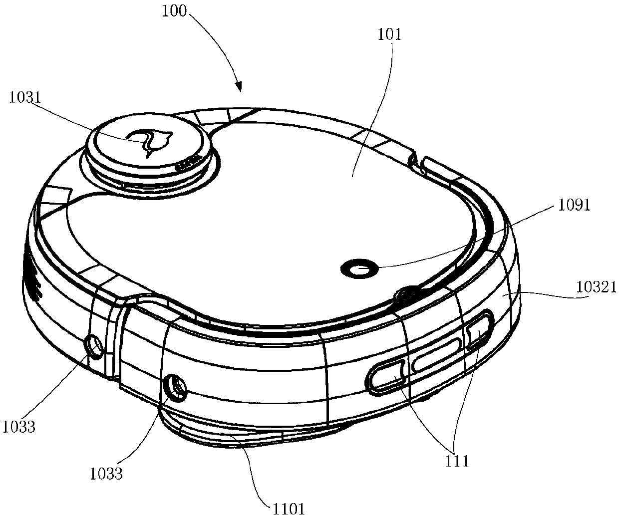
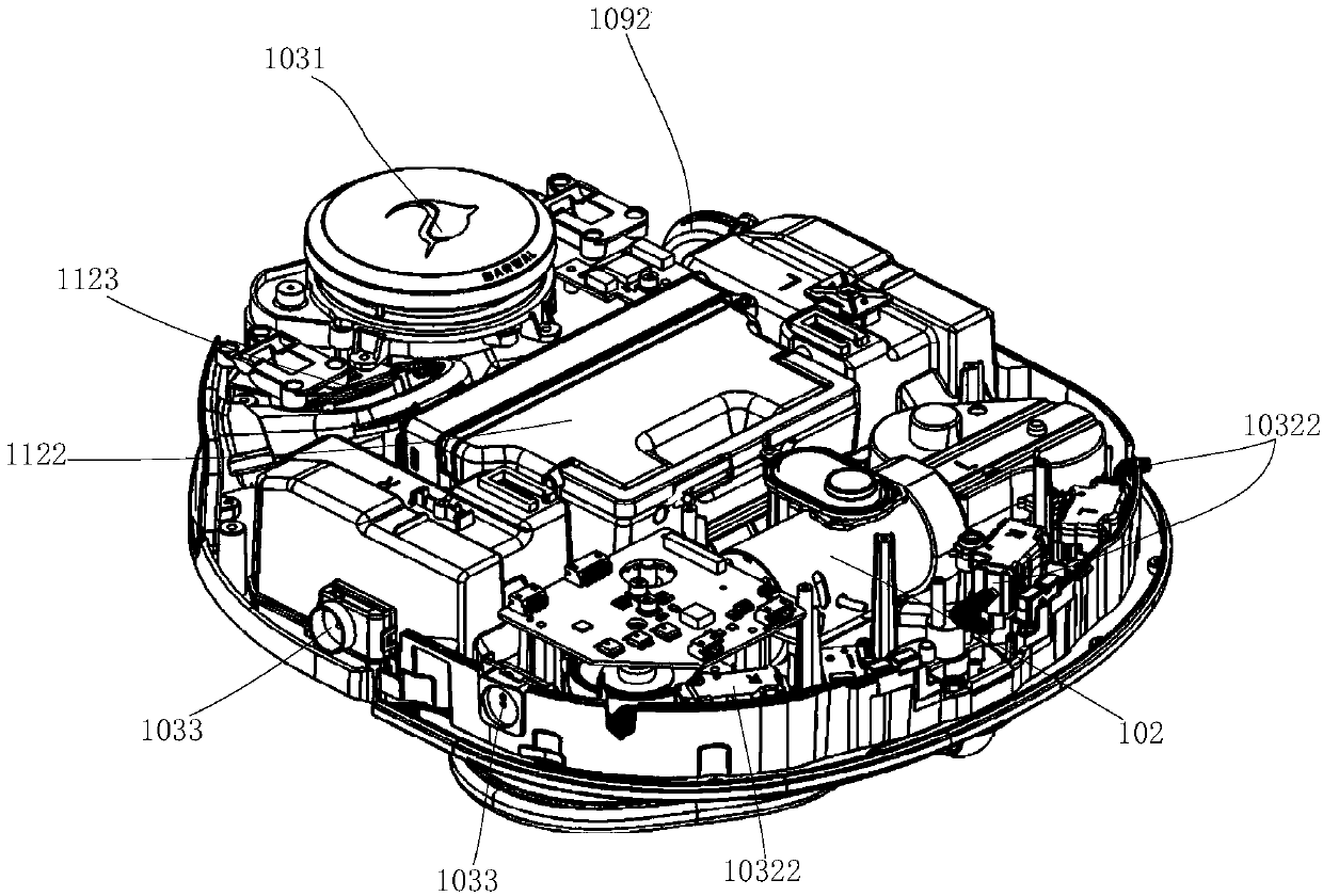
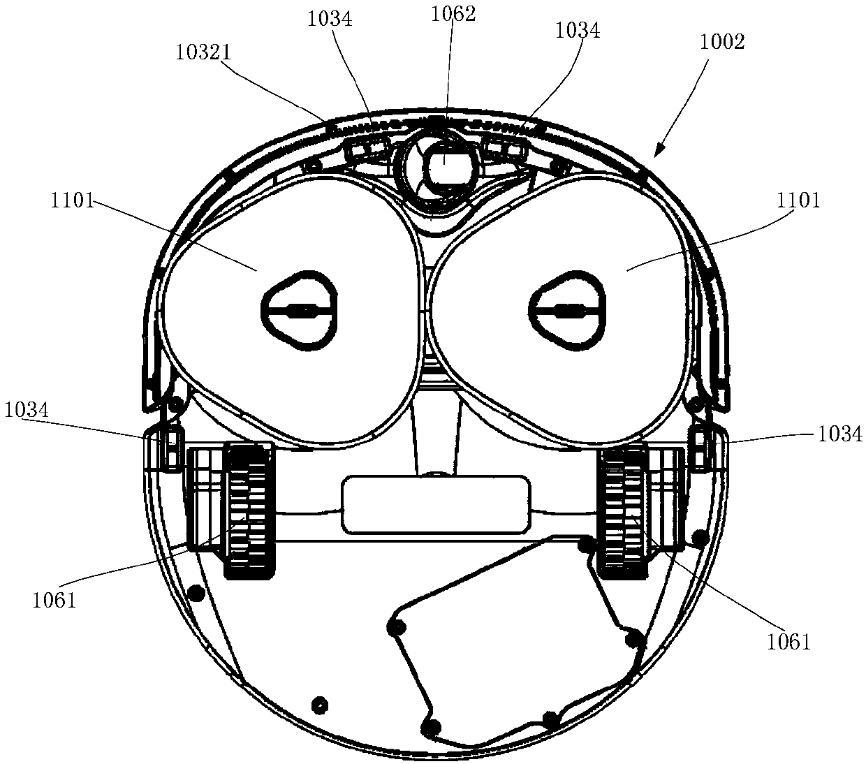
A cleaning robot and cleaning mode technology, applied in the direction of cleaning machinery, cleaning equipment, machine parts, etc., can solve the problems of single function and inapplicability of cleaning robots, and achieve the effect of intelligent work

Active Publication Date: 2019-04-09
YUNJING INTELLIGENCE (SHENZHEN) CO LTD +1
View PDF4 Cites 14 Cited by
  • Summary
  • Abstract
  • Description
  • Claims
  • Application Information

AI Technical Summary

Problems solved by technology

[0004] Existing cleaning robots are either sweeping robots or mopping robots with a single function, so the cleaning robot does not need to identify the cleaning module. When work is required, such as when the user triggers the cleaning robot’s power-on parts, the cleaning robot directly executes the preset cleaning mode
However, this does not apply to cleaning robots with replaceable cleaning modules

Method used


Image

  • Method for controlling cleaning mode, and cleaning robot
  • Method for controlling cleaning mode, and cleaning robot
  • Method for controlling cleaning mode, and cleaning robot

Examples


example 1

[0100] Example 1: There are magnetic parts on the cleaning module and hall sensors on the main body of the robot. When the cleaning module is installed on the main body of the robot, the Hall sensor on the main body of the robot senses the magnetic field of the magnetic part on the cleaning module, so that the Hall sensor changes from high level to low level, and by detecting the low level signal , the cleaning robot can determine that the cleaning module is installed on the main body of the robot.

example 2

[0101] Example 2: A bump is provided on the cleaning module, and a displacement sensor is provided on the main body of the robot. When the cleaning module is installed on the main body of the robot, the bump on the cleaning module triggers the displacement sensor on the main body of the robot to generate a displacement, so that the position sensor generates a preset electrical signal. By detecting the preset electrical signal, the cleaning robot can determine the position of the robot. A cleaning module is installed on the main body.

example 3

[0102] Example 3: A distance sensor is provided at a preset position of the main body of the robot. When the cleaning module is installed on the robot body, the distance sensor at the preset position of the robot body detects the change of the distance value, thereby generating a preset electrical signal, and by detecting the preset electrical signal, the cleaning robot can determine the distance on the robot body The cleaning module is installed.

[0103] Of course, the robot body is used to detect whether the sensor of the cleaning module is installed, and may also be a photosensitive sensor, an image sensor, a voltage sensor, etc., which are not specifically limited in this embodiment of the present invention.

[0104] Step 602: If it is detected that the cleaning module is installed on the main body of the robot, control the cleaning robot to execute a cleaning mode used in conjunction with the cleaning module.

[0105] Wherein, the cleaning mode is the working mode of th...


PUM


Abstract

The embodiment of the invention provides a method for controlling a cleaning mode, and a cleaning robot. The method is used for automatically controlling the cleaning robot to execute a cleaning modecorresponding to a cleaning module. The method provided by the embodiment of the invention comprises the following steps: detecting whether the cleaning module is mounted on a robot body or not; if yes, controlling the cleaning robot to execute the cleaning mode matched with the cleaning module, wherein the cleaning module is a component for cleaning the floor, and the cleaning mode is a working mode of the cleaning robot. Thus, the cleaning robot is automatically controlled to execute the cleaning mode corresponding to the cleaning module, so that the cleaning robot works intelligently.

Description

technical field [0001] The invention relates to the field of smart home equipment, in particular to a method for controlling a cleaning mode and a cleaning robot. Background technique [0002] The cleaning robot is used to clean the floor. The bottom of the cleaning robot is provided with a cleaning module and driving wheels, driven by the driving wheels, the cleaning robot can move on the ground. Through the cleaning module, the cleaning robot can clean the ground. [0003] Existing cleaning robots are often sweeping robots, and the bottom of the sweeping robot is provided with a sweeping brush and a dust suction port, the ground is cleaned by the sweeping brush, and the garbage on the ground is sucked through the dust suction port. Alternatively, the cleaning robot is a mopping robot, and a mop is pasted on the bottom of the mopping robot, and the ground is mopped by the mop. [0004] Existing cleaning robots are either sweeping robots or mopping robots with a single fu...

Claims


Application Information

Patent Timeline
Patent Type & Authority Applications(China)
IPC IPC(8): A47L11/24A47L11/282A47L11/40
CPCA47L11/24A47L11/282A47L11/40A47L11/4011A47L11/4013A47L11/4094A47L11/4036A47L2201/06A47L2201/04A47L9/2805G01S17/931G05D1/0219G05D1/0225A47L9/1409A47L11/28A47L11/4002
Inventor 李畅
Owner YUNJING INTELLIGENCE (SHENZHEN) CO LTD
Learn More