A garden pond salvage boat in a scenic spot
A technology for salvaging boats and gardens, which is applied to special-purpose ships, general water supply conservation, and cleaning of open water surfaces. It can solve problems that affect the beauty of the lake surface, troublesome, time-consuming and labor-intensive problems, and achieve the goal of reducing the intensity of unloading work for employees. Effect
- Summary
- Abstract
- Description
- Claims
- Application Information
AI Technical Summary
Problems solved by technology
Method used
Image
Examples
Embodiment 1
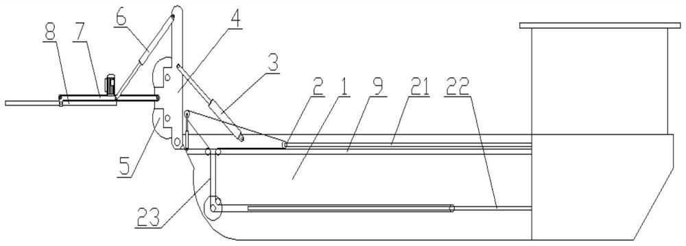
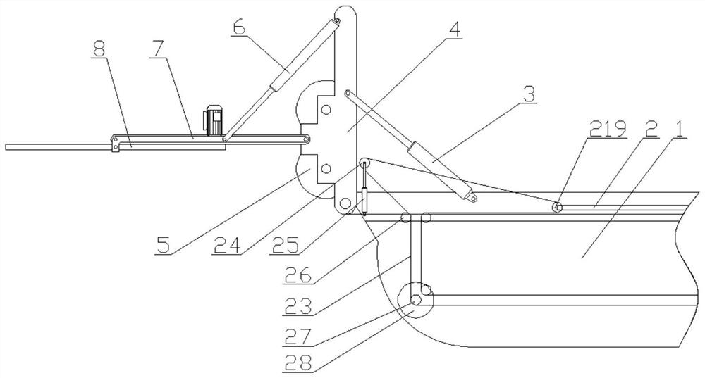
[0030]Such asfigure 1 Shown; a scenic garden pond salvage boat, including a salvage hull 1, the salvage hull 1 is hinged with a fixed frame 4 and an adjusting cylinder 3, the power end of the adjusting cylinder 3 is hinged on the fixed frame 4, the The fixed frame 4 is provided with an extrusion device 5; the fixed frame 4 is hinged with a hinged bracket and an angle cylinder 6. The power end of the angle cylinder 6 is hinged on the hinged bracket, and the hinged bracket is provided with a conveyor 7 and Shearing device 8, the feed end of the conveyor 7 is matched with the shearing device 8, the discharge end of the conveyor 7 is set at the feed port of the extrusion device 5; the salvage hull 1 is provided with a regulating and conveying device 2 and a holding plate 9, the working end of the adjusting and conveying device 2 is set above the holding plate 9, and the adjusting end of the adjusting and conveying device 2 is set below the holding plate 9; the shearing device 8 includes...
Embodiment 2
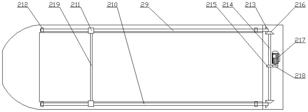
[0033]On the basis of Embodiment 1, the adjusting and conveying device 2 includes an upper adjusting mechanism 21, a lower adjusting mechanism 22, and a conveying adjusting mechanism 23. The upper adjusting mechanism 21 is arranged above the holding plate 9, and the lower adjusting mechanism 22 It is arranged below the material-bearing plate 9. The adjustment positions of the upper adjustment mechanism 21 and the lower adjustment mechanism 22 are both connected to the conveying adjustment mechanism 23. The conveying adjustment mechanism 23 includes a lifting roller 24, a power roller 27, a conveying motor 28, Conveyor belt and a number of guide rollers 26, two lifting cylinders 25 are fixed on the bearing plate 10, the power ends of the two lifting cylinders 25 are respectively connected to one end of the lifting roller 24, the lifting roller 24 is arranged in the squeezing device 5 Below the discharge port; one end of the power roller 27 is connected to the conveying motor 28, and ...
Embodiment 3
[0036]On the basis of Embodiment 2, the shear groove 84 is provided with an inclined material guide surface 85 on one side close to the shear plate fixing frame 86, and the bottom of the shear plate fixing frame 86 is provided with a bracket 87; A shearing slope 185 is provided at one end of the plate 83 away from the bottom of the shearing plate fixing frame 86, and the distance between the adjacent shearing grooves 84 is 20mm to 60mm; the pressing device 5 is a pair of roller compactor, so A scraper 51 is provided on one side of the roller compactor, and the ratio of the length B of the shearing plate 83 to the length A of the shearing groove 84 is 1:2 to 2:3.
[0037]The oblique material guide surface 85 is provided on the side of the shearing groove 84 close to the shear plate fixing frame 86, so that the surface facing the stem of the lotus leaf will not hang the stem of the lotus leaf. The reason is that the stem of the lotus leaf is cut off. After that, the lotus root thread wil...
PUM
 Abstract
Description
Claims
Application Information
 - R&D
- Intellectual Property
- Life Sciences
- Materials
- Tech Scout
- Unparalleled Data Quality
- Higher Quality Content
- 60% Fewer Hallucinations
Browse by: Latest US Patents, China's latest patents, Technical Efficacy Thesaurus, Application Domain, Technology Topic, Popular Technical Reports.
© 2025 PatSnap. All rights reserved.Legal|Privacy policy|Modern Slavery Act Transparency Statement|Sitemap|About US| Contact US: help@patsnap.com


