Graphene heating based assembled background wall

A technology of graphene and background wall, applied in the field of background wall, can solve the problems of poor practicability, difficult to replace the background plate, non-removable background plate, etc., and achieve the effect of convenient movement and temperature increase

Active Publication Date: 2019-04-09
SICHUAN ANDGEM GRAPHENE TECH CO LTD
5 Cites 1 Cited by

AI-Extracted Technical Summary

Problems solved by technology

[0004] Most of the existing background boards are non-removable and fixed on the wall. Once the background board is installed, i...

Method used

The background plate of the present invention is an integral structure that is compounded by the front panel and the back panel, the concrete material of the front panel is silica gel, and the inside of the front panel is fixedly equipped with a disc-shaped heating sheet, and the heating sheet generates heat and passes through the The front panel radiates the interior of the room to increase the temperature inside the room; the present invention is provided with a splicing device on the rear side of the frame, the splicing device includes a second screw and a ferrule, and the upper and lower sides of the second screw are symmetrically provided with two rotation directions The opposite external thread, and the second screw rod is installed on one side of the frame in rotation, and there are two ferrules, which are fixedly installed on the other side of the frame; the second screw rod is threaded with a second screw sleeve, and the second screw The upper and lower sides of the sleeve are symmetrically threaded and connected with two second screw sleeves, the second screw sleeves are fixedly installed with a hook that coopera...

Abstract

The invention discloses a graphene heating based assembled background wall. The assembled background wall comprises a rack and a background plate, wherein the left and right sides of the background plate are fixedly mounted on the inner side of the rack respectively, two storage cavities are symmetrically formed in the left and right sides of the front part of the background plate, and a pluralityof partition boards are fixedly mounted in each storage cavity and divide the storage cavity into multiple cavities; the background plate is of an integrated structure formed by compositing a front panel and a back plate, a disc-shaped heating piece is fixedly mounted in the front panel, two insulation plates are symmetrically and fixedly mounted on the left and right sides of the rear part of the back plate, and a plurality of magnets are uniformly and fixedly mounted on each insulation plate. The background plate is of the integrated structure formed by compositing the front panel and the back plate, the front panel is specifically prepared from silica gel, the disc-shaped heating piece is fixedly mounted in the front panel, produces heat and radiates the interior of a room through thefront panel, and temperature of the interior of the room is increased.

Application Domain

Covering/liningsSustainable buildings +1

Technology Topic

Agricultural engineeringMagnet +5

Image

  • Graphene heating based assembled background wall
  • Graphene heating based assembled background wall
  • Graphene heating based assembled background wall

Examples

  • Experimental program(3)

Example Embodiment

[0026] Example 1
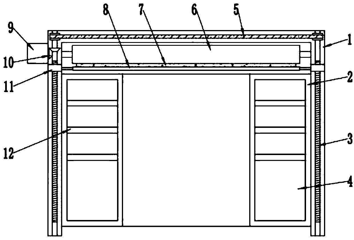
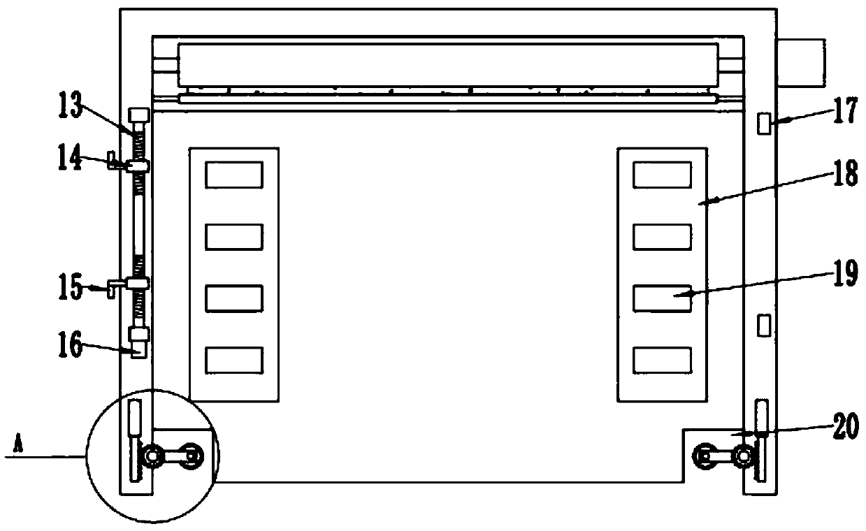
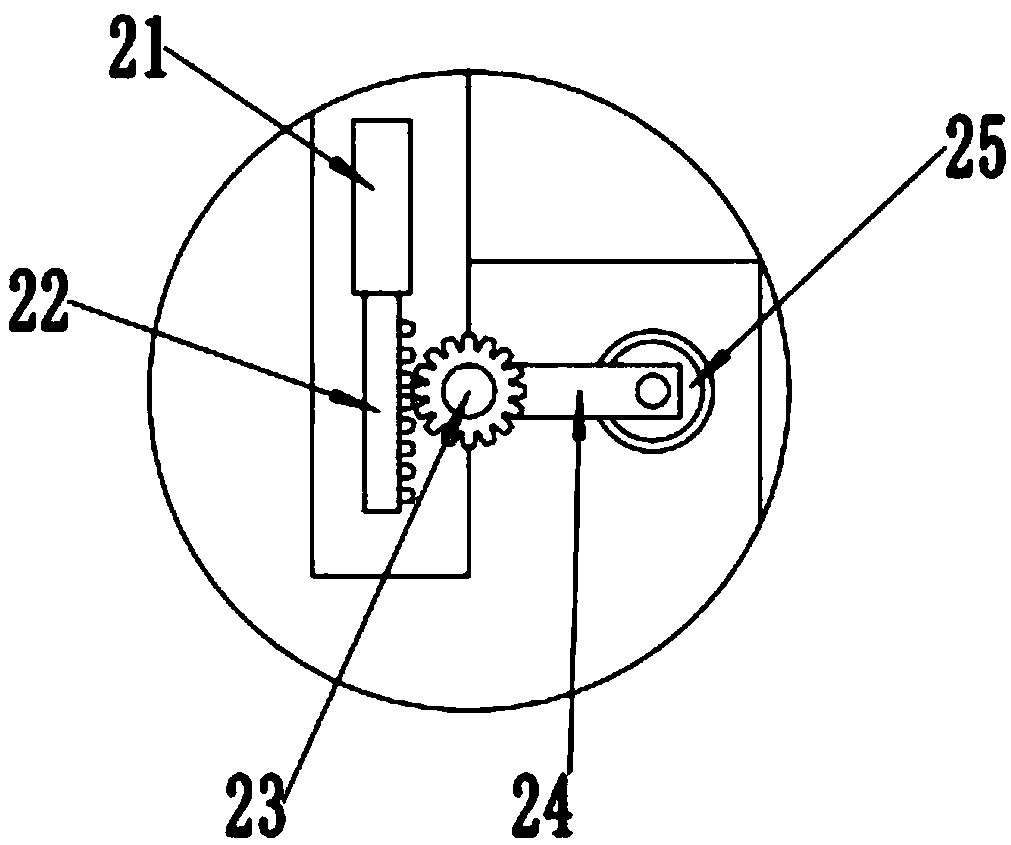
[0027] See Figure 1-4 , A graphene heating assembly background wall, comprising a frame 1 and a background plate 2; the frame 1 is an inverted U-shaped frame structure, and the left and right sides of the background plate 2 are fixedly installed on the inner side of the frame 1, respectively, Two storage cavities 4 are symmetrically provided on the left and right sides of the front part of the background plate 2. A number of partitions 12 are fixedly installed inside the storage chamber 4. The partitions 12 divide the interior of the storage chamber 4 into multiple cavities for placing sundries. The background plate 2 is an integrated structure composed of a front panel and a back panel. The specific material of the front panel is silica gel. A disc-shaped heating plate 26 is fixedly installed inside the front panel. The heating plate 26 generates heat and passes The front panel radiates the interior of the room to increase the internal temperature of the room; the left and right sides of the back panel are symmetrically installed with two heat insulation boards 18, and a number of magnet stickers 19 are evenly fixed and installed on the heat insulation board 18 to avoid The magnetic sticker 19 is demagnetized when the background plate 2 is fixed, and the material of the back plate and the heat insulation plate 18 is specifically rock wool;
[0028] In order to further improve the heating effect, the heating plate 26 is a graphene heating plate. Graphene can improve the electrical conductivity of the heating plate 26, thereby improving the thermal conductivity of the heating plate 26, and can also increase the service life of the heating plate 26, avoiding frequent Replacement and maintenance to reduce economic costs;
[0029] The frame 1 is located on the upper side of the background plate 2 and is rotatably installed with a winding roller 6, on which a decorative cloth 7 is wound. The lower side of the decorative cloth 7 is fixedly connected with a lifting rod 8 through the upper and lower sides of the lifting rod 8. The movement drives the decorative cloth 7 to move up and down, and when the decorative cloth 7 has finished covering the background plate 2, the background plate 2 can be used as a background wall; two first screws 3 are installed on the left and right sides of the rack 1 to rotate symmetrically. , The upper ends of the two first screws 3 are connected by a belt 5, and the two first screws 3 are also threadedly connected with a first screw sleeve 11. The first screw 11 is slidingly connected to the inside of the frame 1, and the lifting rod 8 The left and right ends are fixedly connected with the two first screw sleeves 11 by connecting rods. When the first screw sleeve 11 moves up and down, the lifting rod 8 is driven to move up and down; the frame 1 is also fixedly installed with a first motor 9 The output end of the motor 9 is drivingly connected to one of the first screws 11 through the bevel gear set 10, thereby driving the two first screws 11 to rotate in the same direction at the same time.

Example Embodiment

[0030] Example 2
[0031] See Figure 1-4 , A graphene heating assembly background wall, comprising a frame 1 and a background plate 2; the frame 1 is an inverted U-shaped frame structure, and the left and right sides of the background plate 2 are fixedly installed on the inner side of the frame 1, respectively, Two storage cavities 4 are symmetrically provided on the left and right sides of the front part of the background plate 2. A number of partitions 12 are fixedly installed inside the storage chamber 4. The partitions 12 divide the interior of the storage chamber 4 into multiple cavities for placing sundries. The background plate 2 is an integrated structure composed of a front panel and a back panel. The specific material of the front panel is silica gel. A disc-shaped heating plate 26 is fixedly installed inside the front panel. The heating plate generates heat and passes through the front The panel radiates the interior of the room to increase the internal temperature of the room; the left and right sides of the back panel are symmetrically installed with two heat insulation boards 18, and a number of magnetic stickers 19 are uniformly fixed and installed on the heat insulation board 18 to avoid magnetic The sticker 19 is demagnetized when the background board 2 is fixed, and the material of the back board and the heat insulation board 18 is specifically rock wool;
[0032] In order to further improve the heating effect, the heating plate 26 is a graphene heating plate. Graphene can improve the electrical conductivity of the heating plate 26, thereby improving the thermal conductivity of the heating plate 26, and can also increase the service life of the heating plate 26, avoiding frequent Replacement and maintenance to reduce economic costs;
[0033] The frame 1 is located on the upper side of the background plate 2 and is rotatably installed with a winding roller 6, on which a decorative cloth 7 is wound. The lower side of the decorative cloth 7 is fixedly connected with a lifting rod 8 through the upper and lower sides of the lifting rod 8. The movement drives the decorative cloth 7 to move up and down, and when the decorative cloth 7 has finished covering the background plate 2, the background plate 2 can be used as a background wall; two first screws 3 are installed on the left and right sides of the rack 1 to rotate symmetrically. , The upper ends of the two first screws 3 are connected by a belt 5, and the two first screws 3 are also threadedly connected with a first screw sleeve 11. The first screw 11 is slidingly connected to the inside of the frame 1, and the lifting rod 8 The left and right ends are fixedly connected with the two first screw sleeves 11 by connecting rods. When the first screw sleeve 11 moves up and down, the lifting rod 8 is driven to move up and down; the frame 1 is also fixedly installed with a first motor 9 The output end of the motor 9 is drivingly connected to one of the first screws 11 through the bevel gear set 10, thereby driving the two first screws 11 to rotate in the same direction at the same time.
[0034] The difference between this embodiment and the first embodiment is that a splicing device is provided on the rear side of the frame 1. The splicing device includes a second screw 13 and a ferrule 17, and two symmetrical upper and lower sides of the second screw 13 are provided. The second screw 13 is rotatably installed on one side of the frame 1, and two clamping sleeves 17 are fixedly installed on the other side of the frame 1. The second screw 13 is threaded A second threaded sleeve 14 is connected. The upper and lower sides of the second threaded sleeve 14 are symmetrically threaded with two second threaded sleeves 14. The second threaded sleeve 14 is fixedly installed with a hook 15 that cooperates with the ferrule 17, so The rear side of the frame 1 is also fixedly installed with a second motor 16 that drives the second screw 13 to rotate. When the second motor 16 drives the second screw 13 to rotate clockwise, the two second hooks 15 move back and interact with each other. The card sleeves 17 on the next frame 1 are clamped to each other, so that the two background boards are spliced ​​into one background board.

Example Embodiment

[0035] Example 3
[0036] See Figure 1-4 , A graphene heating assembly background wall, comprising a frame 1 and a background plate 2; the frame 1 is an inverted U-shaped frame structure, and the left and right sides of the background plate 2 are fixedly installed on the inner side of the frame 1, respectively, Two storage cavities 4 are symmetrically provided on the left and right sides of the front part of the background plate 2. A number of partitions 12 are fixedly installed inside the storage chamber 4. The partitions 12 divide the interior of the storage chamber 4 into multiple cavities for placing sundries. The background plate 2 is an integrated structure composed of a front panel and a back panel. The specific material of the front panel is silica gel. A disc-shaped heating plate 26 is fixedly installed inside the front panel. The heating plate generates heat and passes through the front The panel radiates the interior of the room to increase the internal temperature of the room; the left and right sides of the back panel are symmetrically installed with two heat insulation boards 18, and a number of magnetic stickers 19 are uniformly fixed and installed on the heat insulation board 18 to avoid magnetic The sticker 19 is demagnetized when the background board 2 is fixed, and the material of the back board and the heat insulation board 18 is specifically rock wool;
[0037] In order to further improve the heating effect, the heating plate 26 is a graphene heating plate. Graphene can improve the electrical conductivity of the heating plate 26, thereby improving the thermal conductivity of the heating plate 26, and can also increase the service life of the heating plate 26, avoiding frequent Replacement and maintenance to reduce economic costs;
[0038] The frame 1 is located on the upper side of the background plate 2 and is rotatably installed with a winding roller 6, on which a decorative cloth 7 is wound. The lower side of the decorative cloth 7 is fixedly connected with a lifting rod 8 through the upper and lower sides of the lifting rod 8. The movement drives the decorative cloth 7 to move up and down, and when the decorative cloth 7 has finished covering the background plate 2, the background plate 2 can be used as a background wall; two first screws 3 are installed on the left and right sides of the rack 1 to rotate symmetrically. , The upper ends of the two first screws 3 are connected by a belt 5, and the two first screws 3 are also threadedly connected with a first screw sleeve 11. The first screw 11 is slidingly connected to the inside of the frame 1, and the lifting rod 8 The left and right ends are fixedly connected with the two first screw sleeves 11 by connecting rods. When the first screw sleeve 11 moves up and down, the lifting rod 8 is driven to move up and down; the frame 1 is also fixedly installed with a first motor 9 The output end of the motor 9 is drivingly connected to one of the first screws 11 through the bevel gear set 10, thereby driving the two first screws 11 to rotate in the same direction at the same time.
[0039] A splicing device is provided on the rear side of the frame 1. The splicing device includes a second screw 13 and a ferrule 17. The upper and lower sides of the second screw 13 are symmetrically provided with two external threads with opposite rotation directions, and the second screw 13 It is rotatably installed on one side of the frame 1, and there are two ferrules 17 and fixedly installed on the other side of the frame 1. The second screw 13 is threadedly connected with a second screw sleeve 14, the second screw sleeve 14 Two second screw sleeves 14 are screwed symmetrically on the upper and lower sides. The second screw sleeve 14 is fixedly installed with a hook 15 that cooperates with the clamping sleeve 17, and the rear side of the rack 1 is also fixedly installed to drive the first When the second motor 16 rotates by the two screw rods 13 and the second motor 16 drives the second screw rod 13 to rotate clockwise, the two second hooks 15 move back and engage with the clamping sleeve 17 on the next frame 1 , The two background boards are spliced ​​into one background board.
[0040] In order to facilitate the movement of the background board, the difference between this embodiment and the second embodiment is that an electric push rod 21 is fixedly installed at the lower end of the frame 1, and a rack 22 is fixedly connected to the output end of the electric push rod 21. The frame 1 is rotatably mounted on the inner side of the rack 22 with a round gear 23, which meshes with the rack 22, and a rotating rod 24 is fixedly mounted on the round gear 23. The other end of the rotating rod 24 is rotatably mounted with a caster 25. Change the length of the electric push rod 21 to move the rack 22 up and down, thereby driving the round gear 23 to rotate, and the round gear 23 drives the rotating rod 24 to rotate. When the rotating rod 24 is in a vertical state, the caster 25 is in contact with the ground to facilitate the background The board moves; the left and right sides of the lower part of the background board 2 are symmetrically provided with two grooves 20 for storing casters 25.
[0041] The background plate of the present invention is an integrated structure composed of a front plate and a back plate. The specific material of the front plate is silica gel. The inside of the front plate is fixedly installed with a disc-shaped heating plate. The heating plate generates heat and is aligned through the front plate. The interior of the room is radiated to increase the internal temperature of the room; the present invention is provided with a splicing device on the rear side of the frame, and the splicing device includes a second screw and a ferrule. The upper and lower sides of the second screw are symmetrically provided with two outer surfaces with opposite rotation directions. The second screw is rotatably installed on one side of the frame, and there are two ferrules, and they are fixedly installed on the other side of the frame; the second screw is threadedly connected with a second screw sleeve, Two second screw sleeves are connected with two symmetrical threads on both sides. The second screw sleeve is fixedly installed with a hook that cooperates with the clamping sleeve. The rear side of the frame is also fixedly installed with a second motor that drives the second screw to rotate. When the second motor drives the second screw to rotate clockwise, the two second hooks move back and engage with the card sleeves on the next frame, so that the two background plates are spliced ​​into one background plate; The lower end of the frame is fixedly installed with an electric push rod, and the output end of the electric push rod is fixedly connected with a rack. A circular gear is installed on the inner side of the rack for rotation. The circular gear meshes with the rack, and the circular gear is fixedly installed Rotate the lever, the other end of the rotating lever rotates and the caster is installed. By changing the length of the electric push rod, the rack can move up and down, thereby driving the round gear to rotate. The round gear drives the rotating rod to rotate. When the rotating rod is in a vertical state, the caster Contact with the ground to facilitate the movement of the background board.

PUM

no PUM

Description & Claims & Application Information

We can also present the details of the Description, Claims and Application information to help users get a comprehensive understanding of the technical details of the patent, such as background art, summary of invention, brief description of drawings, description of embodiments, and other original content. On the other hand, users can also determine the specific scope of protection of the technology through the list of claims; as well as understand the changes in the life cycle of the technology with the presentation of the patent timeline. Login to view more.

Similar technology patents

Boiler condensed water recovery process

Owner:GUIZHOU ANSHUN JIAYU NEW MATERIALS

Classification and recommendation of technical efficacy words

  • easy to move
  • increase temperature

Backpack medlar-picking machine

InactiveCN101473731Aeasy to movenovel structure
Owner:CHINA AGRI UNIV

Stream media broadcasting method and system

InactiveCN103763637AEasy to transfereasy to move
Owner:CHINA NSTV

Hot-blast stove of biomass energy source

InactiveCN101907354Astructural scienceEasy to move
Owner:SICHUAN HUINONG MACHINERY

Water drainage and gas production simulated experimental device

InactiveCN101806202Aeasy to move
Owner:CHINA UNIV OF PETROLEUM (EAST CHINA)

Hydraulic self-moving steel mould trolley and construction method thereof

ActiveCN103437782AFlexible removal locationeasy to move
Owner:CHINA THREE GORGES CORPORATION +1

Aeroengine materials hot end environment experimental simulation method and device

InactiveCN1546974Aincrease temperatureSimulated high temperature
Owner:NORTHWESTERN POLYTECHNICAL UNIV

Commercial high-efficiency energy-saving gas burner

InactiveCN101619852Aincrease temperaturefierce firepower
Owner:HEFEI CENTURIES FIVE STAR CATERING EQUIP LIABILITY

Oven

Owner:泰克厨房有限责任公司
Why Eureka
Try Eureka