

Pump body structure of rotary cylinder piston compressor and rotary cylinder piston compressor
A compressor and piston technology, which is applied in the field of pump body structure and rotary cylinder piston compressor, can solve the problems of easy wear and tear of the matching structure between the cylinder and the outer circle, and achieve the effects of preventing stress concentration, reducing wear and good lubricating effect
- Summary
- Abstract
- Description
- Claims
- Application Information
AI Technical Summary
Problems solved by technology
Method used
Image

Examples
Embodiment Construction
[0037] The technical solutions of the present invention will be clearly and completely described below in conjunction with the accompanying drawings. Apparently, the described embodiments are some of the embodiments of the present invention, but not all of them. Based on the embodiments of the present invention, all other embodiments obtained by persons of ordinary skill in the art without making creative efforts belong to the protection scope of the present invention.
[0038] In addition, the technical features involved in the different embodiments of the present invention described below may be combined with each other as long as there is no conflict with each other.
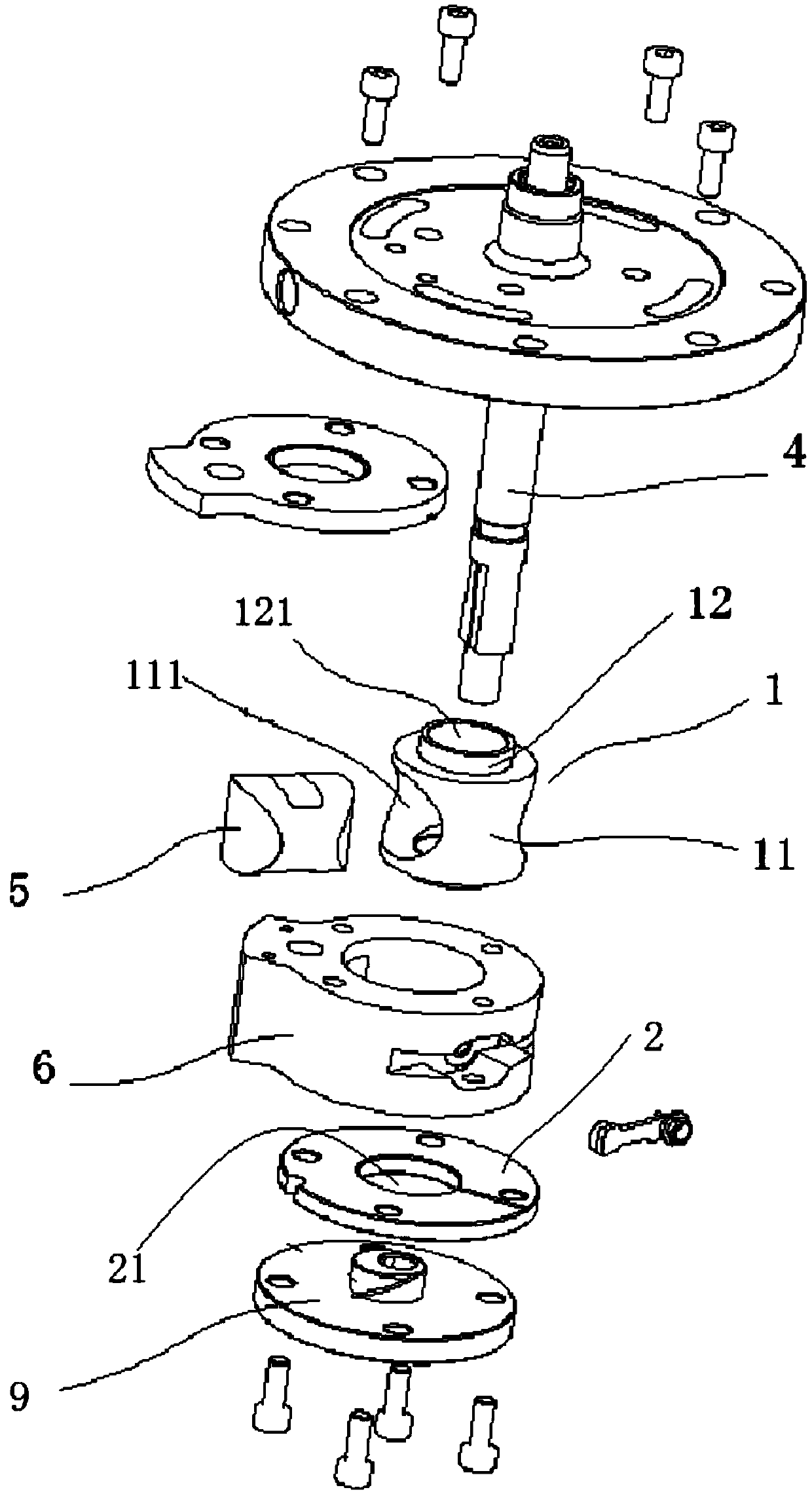
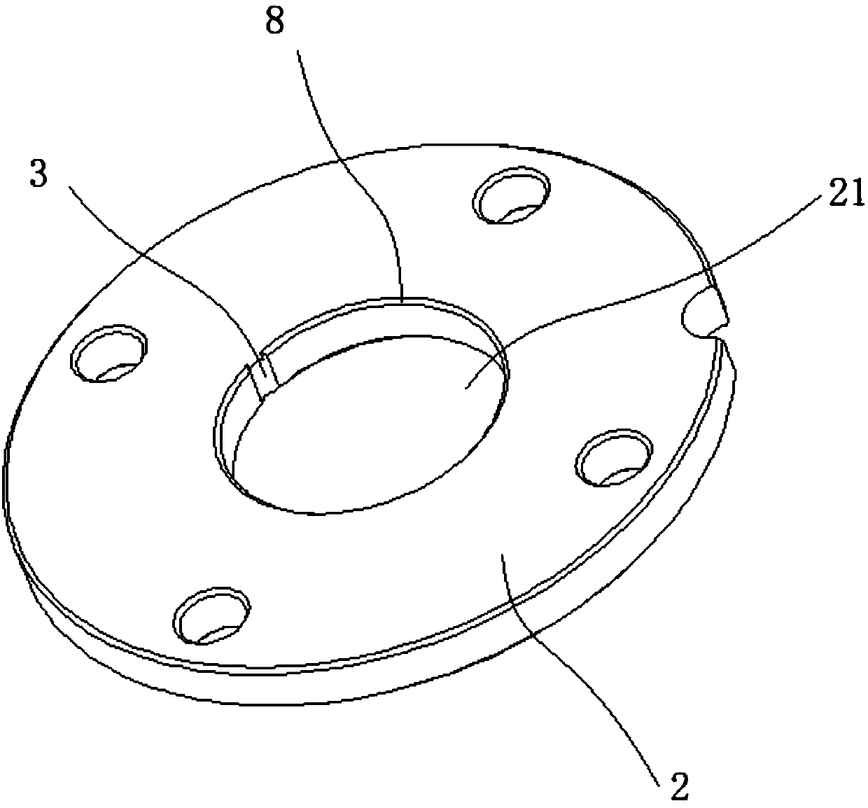
[0039] like Figure 2-Figure 6As shown, this embodiment provides a pump body structure of a rotary cylinder piston 5 compressor, including a cylinder 1 , an outer circular matching structure 2 , an oil guide groove 3 , a rotating shaft 4 , a piston 5 and a cylinder liner 6 .
[0040] The cylinder 1 includes ...
PUM
 Abstract
Description
Claims
Application Information