
Rotary multifunctional valve core

A multi-functional valve and rotary technology, applied in the field of sanitary ware, can solve the problems of complex design, single function and complicated operation of the waterway control part, and achieve the effect of simple structure, diversified functions and easy operation and adjustment

Pending Publication Date: 2019-04-09
NINGBO SAIDI SPOOL TECH CO LTD
View PDF4 Cites 1 Cited by
  • Summary
  • Abstract
  • Description
  • Claims
  • Application Information

AI Technical Summary

Problems solved by technology

[0003] In the existing traditional waterway control, at least two spools are needed to realize flow regulation, switch and function switching, that is, one spool is used for waterway switching, and the other spool is used for flow regulation and water temperature regulation. In this way, not only The design of the waterway control part of the product is complicated, the cost is high, and the operation is also relatively complicated, and the function is relatively simple, so there is still room for further improvement. Now a switch, flow, water temperature adjustment and water diversion function switching are required. Rotary multi-function spool

Method used


Image

  • Rotary multifunctional valve core
  • Rotary multifunctional valve core
  • Rotary multifunctional valve core

Examples


Embodiment Construction

[0023] Any feature disclosed in this specification, unless specifically stated, can be replaced by other alternative features that are equivalent or have similar purposes. That is, unless expressly stated otherwise, each feature is one example only of a series of equivalent or similar features.

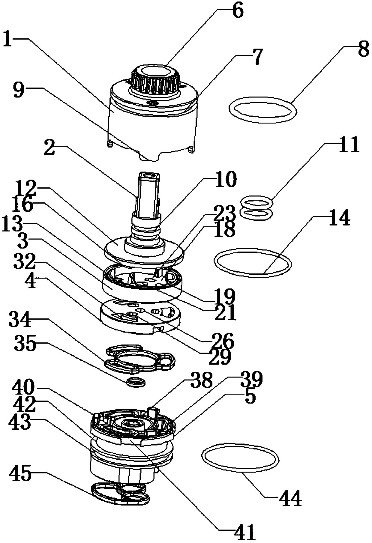
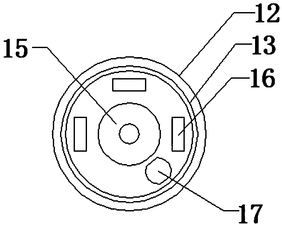
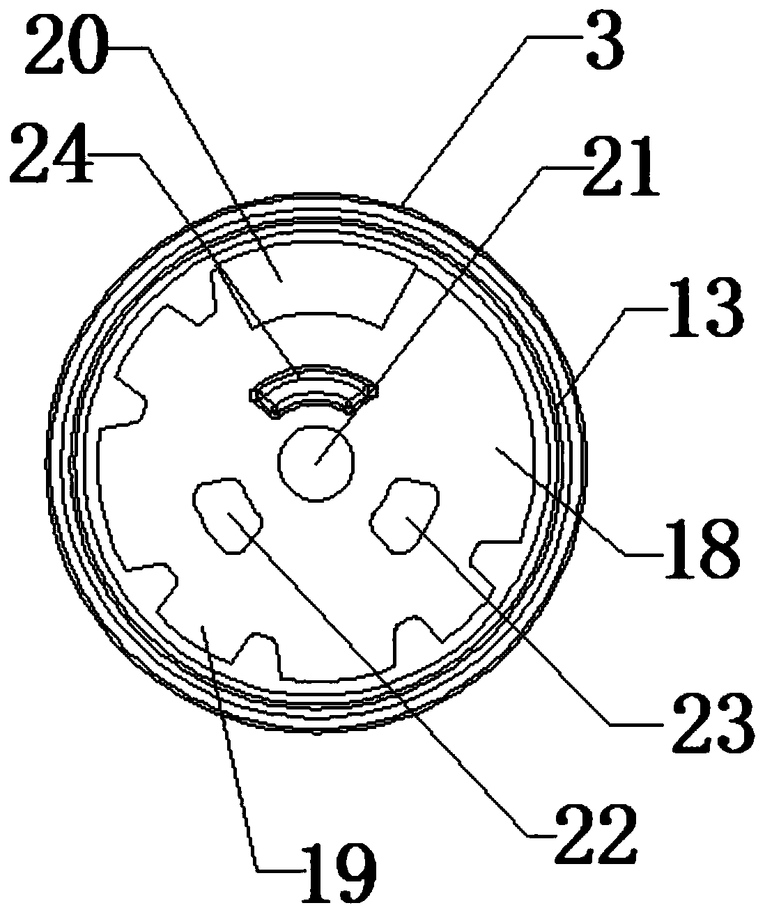
[0024] Such as Figure 1-9A rotary multifunctional valve core shown includes a casing 1, a handle 2, a ceramic moving piece 3, a ceramic static piece 4 and a base 5, and a first ring groove 7 is set inside the top outside of the casing 1, and a first ring groove 7 is arranged on the outside of the first ring A first sealing O-ring 8 is arranged in the groove 7, and two second ring grooves 10 are arranged in sequence on the handle 2, and a second sealing O-ring 11 is arranged in the second ring groove 10, and the top of the ceramic moving piece 3 A third ring groove 13 is arranged inside, a third sealing O-ring 14 is arranged in the third ring groove 13, a fourth ring groove 43 is arr...


PUM


Abstract

The invention discloses a rotary multifunctional valve core. The rotary multifunctional valve core comprises a shell, a handle, a ceramic moving piece, a ceramic static piece and a base. A first annular groove is formed in the outer side of the top of the shell. A first sealing O-type ring is arranged in the first annular groove. Two second annular grooves are formed in the handle in sequence. Second sealing O-type rings are arranged in the second annular grooves. A third annular groove is formed in the top of the ceramic moving piece. A third sealing O-type ring is arranged in the third annular groove. A fourth annular groove is formed in the outer side of the base. A fourth sealing O-type ring is arranged in the fourth annular groove. The handle, the ceramic moving piece and the ceramicstatic piece are arranged in the shell in sequence. The handle is arranged above the ceramic moving piece. The ceramic moving piece is arranged above the ceramic static piece. The shell is arranged onthe base. First sealing rubber is arranged at the bottom of the base. The rotary multifunctional valve core is simple in structure, can be opened and closed, realizes the function switching of flow and water temperature adjustment and water distribution, reduces the cost, is diversified in function and convenient to operate and adjust, and can be beneficially popularized.

Description

technical field [0001] The invention relates to the field of sanitary ware, in particular to a rotary multifunctional valve core. Background technique [0002] The spool is a valve part that uses its movement to realize the basic functions of direction control, pressure control or flow control. [0003] In the existing traditional waterway control, at least two spools are needed to realize flow regulation, switch and function switching, that is, one spool is used for waterway switching, and the other spool is used for flow regulation and water temperature regulation. In this way, not only The design of the waterway control part of the product is complicated, the cost is high, and the operation is also relatively complicated, and the function is relatively single, so there is still room for further improvement. Now a switch, flow, water temperature adjustment and water separation function switching are required. Rotary multi-function spool. Contents of the invention [00...

Claims


Application Information

Patent Timeline
Patent Type & Authority Applications(China)
IPC IPC(8): F16K3/08F16K3/314F16K27/04
CPCF16K3/085F16K3/314F16K27/045
Inventor 竺狄
Owner NINGBO SAIDI SPOOL TECH CO LTD
Learn More