Method for testing chip parameters at different temperatures

A test method and chip technology, which is applied in the direction of electronic circuit testing, measuring electricity, measuring devices, etc., can solve the problems of high cost, large human resources, low efficiency, etc., and achieve the effect of reducing workload and improving test efficiency

Inactive Publication Date: 2019-04-09
BEIJING SMARTCHIP MICROELECTRONICS TECH COMPANY +1
View PDF9 Cites 9 Cited by
  • Summary
  • Abstract
  • Description
  • Claims
  • Application Information

AI Technical Summary

Problems solved by technology

[0005] However, the inventors of the present application found that: the existing testing method consumes a large amount of human resources, and the cost is high; and it needs to manually set the temperature many times, which is inefficient

Method used


Image

  • Method for testing chip parameters at different temperatures
  • Method for testing chip parameters at different temperatures

Examples


Embodiment 1

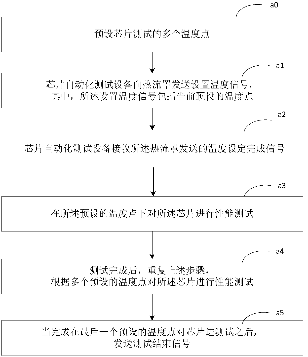
[0024] like figure 1 Shown is a flowchart of a method for testing chip parameters at different temperatures according to a preferred embodiment of the present invention. The test method utilizes a heat flow shield and chip automated testing equipment. The heat flow shield includes a sensor, and the sensor is used to measure the chip temperature. The chip automatic testing equipment is connected with the chip. The execution subject in this embodiment is the automatic chip testing equipment, which specifically includes the following steps.

[0025] In step a1, the chip automated testing equipment sends a set temperature signal to the heat flow shield, wherein the set temperature signal includes a currently preset temperature point.

[0026] In step a2, the chip automated testing equipment receives the temperature setting completion signal sent by the heat flow cover, wherein the temperature setting completion signal is: after the heat flow cover receives the set temperature sig...

Embodiment 2

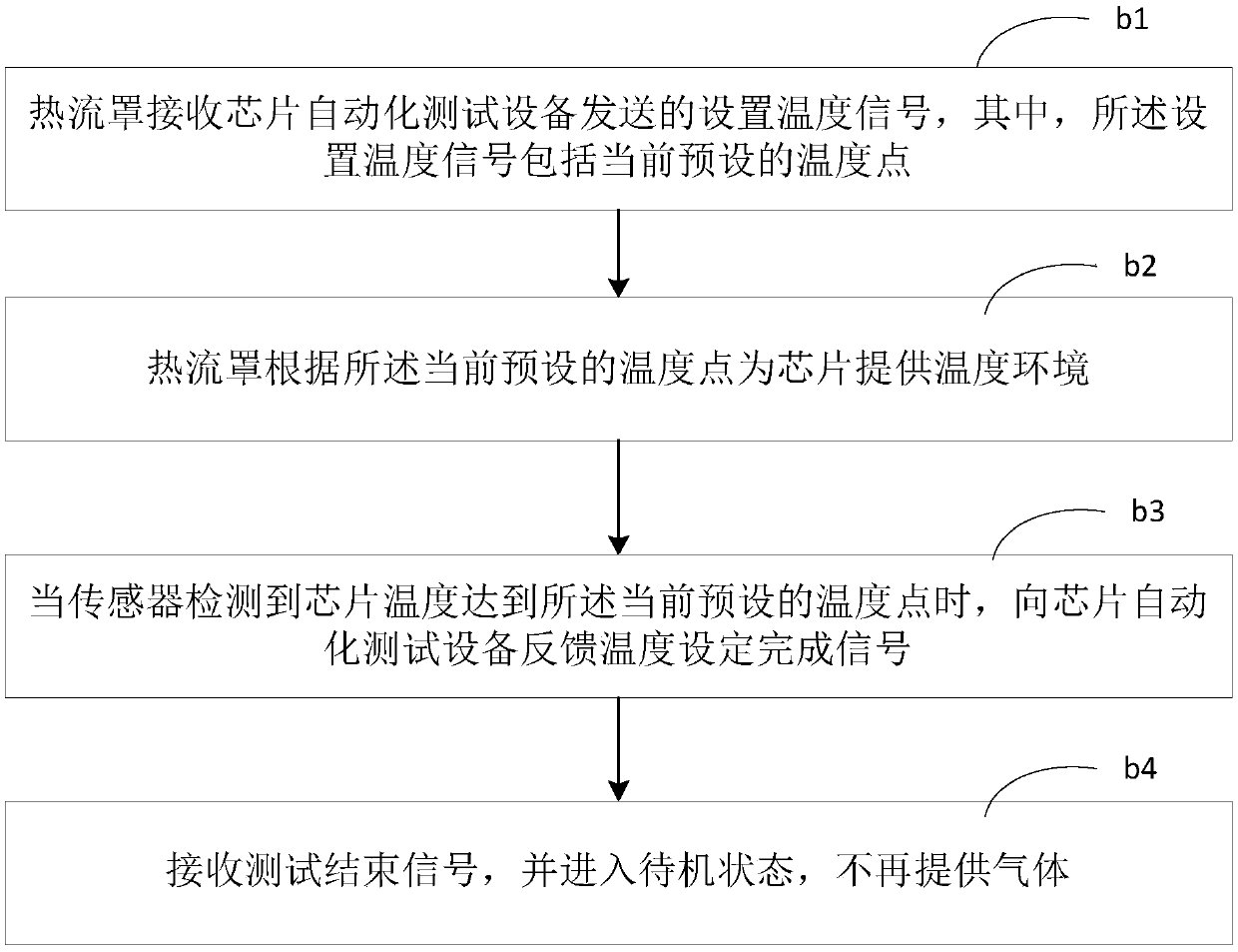
[0036] like figure 2 Shown is a flow chart of a method for testing chip parameters at different temperatures according to another preferred embodiment of the present invention. The test method utilizes a heat flow shield and chip automated testing equipment. The heat flow shield includes a sensor, and the sensor is used to measure the chip temperature. The chip automatic testing equipment is connected with the chip. The execution body in this embodiment is a heat flow shield, which specifically includes the following steps.

[0037] In step b1, the heat flow shield receives a set temperature signal sent by the chip automation test equipment, wherein the set temperature signal includes a currently preset temperature point.

[0038] In step b2, the heat flow shield provides a temperature environment for the chip according to the current preset temperature point.

[0039] Specifically, after the heat flow hood is turned on, the dry compressed air is sucked in through the pipelin...


PUM


Abstract

The invention discloses a method for testing chip parameters at different temperatures. The method comprises the following steps: chip automation testing equipment sends a temperature setting signal to a heat flow cover, wherein the temperature setting signal comprises a current preset temperature point; a temperature setting completion signal sent by the heat flow cover is received, wherein the temperature setting completion signal is a signal fed back to the chip automation testing equipment by the heat flow cover when the temperature of a chip reaches the preset temperature point after theheat flow cover provides an environment temperature for the chip according to the current preset temperature point and detects the temperature of the chip after receiving the temperature setting signal; performance testing is performed on the chip; and the steps are repeated after the testing is completed, and the performance testing is performed on the chip according to a plurality of preset temperature points. According to the method for testing the chip parameters at the different temperatures, the workload of workers can be reduced, all tests can be completed by periodically replacing thechip, and the test efficiency of the chip is improved.

Description

technical field [0001] The invention relates to testing of chip parameters, in particular to a testing method of chip parameters at different temperatures. Background technique [0002] With the development of modern technology, people have higher and higher requirements for the quality of chips. The operating temperature range is an important parameter of the chip. Before mass production, it is necessary to thoroughly test the temperature drift of the function and performance parameters of the chip, collect data, and ensure that the operating temperature range of the chip meets the quality requirements. [0003] The existing measurement method is to manually set the test temperature by relying on the test environment temperature control equipment (heat flow cover). Indispensable instruments and equipment for testing, failure analysis, and reliability evaluation are widely used in semiconductor companies. Specifically, a sensor for measuring the temperature of the chip is...

Claims


Application Information

Patent Timeline
IPC IPC(8): G01R31/28
CPCG01R31/2874
Inventor 李秀全唐晓柯李德建关媛
Owner BEIJING SMARTCHIP MICROELECTRONICS TECH COMPANY
Why Eureka
Try Eureka