Grid-connected inverter control method combining SVPWM with sliding mode variable structure

A sliding mode variable structure and control method technology, which is applied in the direction of irreversible DC power input conversion to AC power output, single-network parallel feeding arrangement, etc., can solve the problems of inability to effectively guarantee system control accuracy, low PWM tracking progress, etc. Current coupling control deviation and other issues, to achieve good practicability, good dynamic and steady-state performance, and reduce the effect of control deviation

Inactive Publication Date: 2019-04-09
ZHANGZHOU POWER SUPPLY COMPANY STATE GRID FUJIANELECTRIC POWER +1
View PDF0 Cites 4 Cited by
  • Summary
  • Abstract
  • Description
  • Claims
  • Application Information

AI Technical Summary

Problems solved by technology

[0005] The traditional PWM tracking progress is low, the switching loss is high, and it is difficult to realize digitalization; the sliding mode variable structure control can maintain the stability and robustness of the system well, but it cannot effectively guarantee the control accuracy of the system. The dq axis current coupling There is control deviation

Method used


Image

  • Grid-connected inverter control method combining SVPWM with sliding mode variable structure
  • Grid-connected inverter control method combining SVPWM with sliding mode variable structure
  • Grid-connected inverter control method combining SVPWM with sliding mode variable structure

Examples


Embodiment Construction

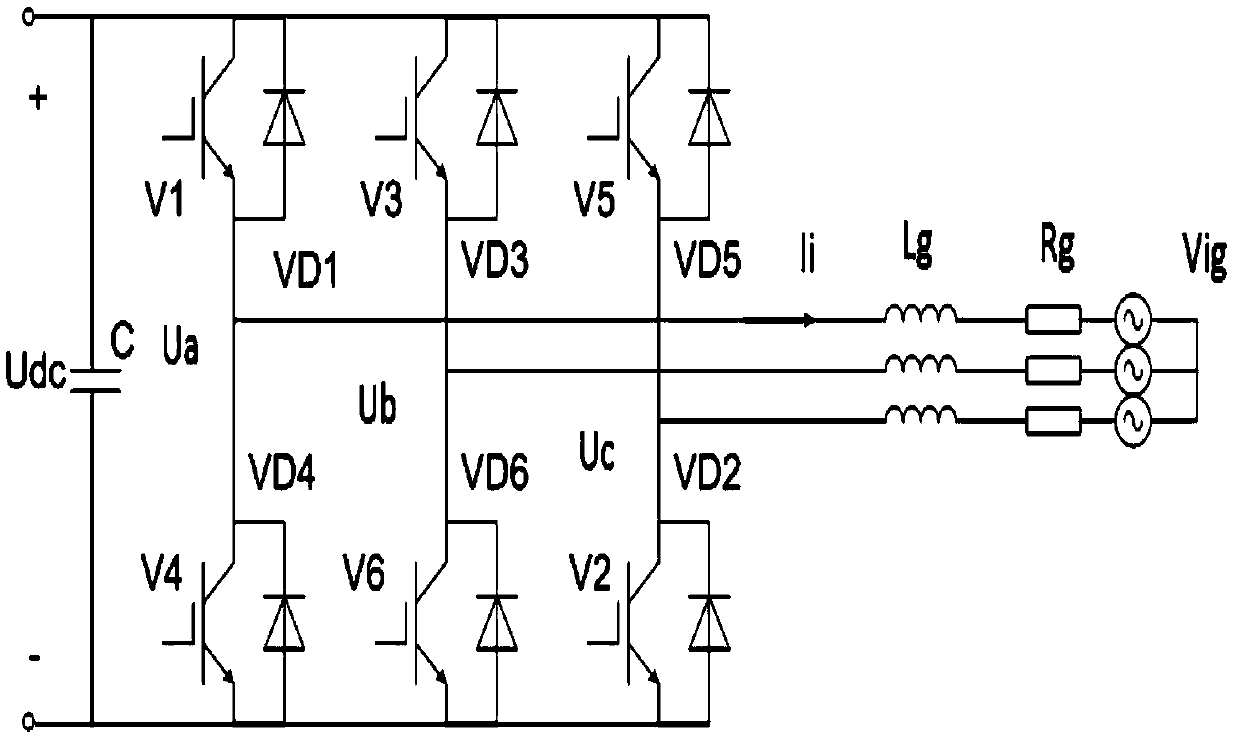
[0033] Examples, see Figure 1 to Figure 4 As shown, a kind of SVPWM of the present invention and the grid-connected inverter control method of sliding mode variable structure combination, it comprises the following steps:

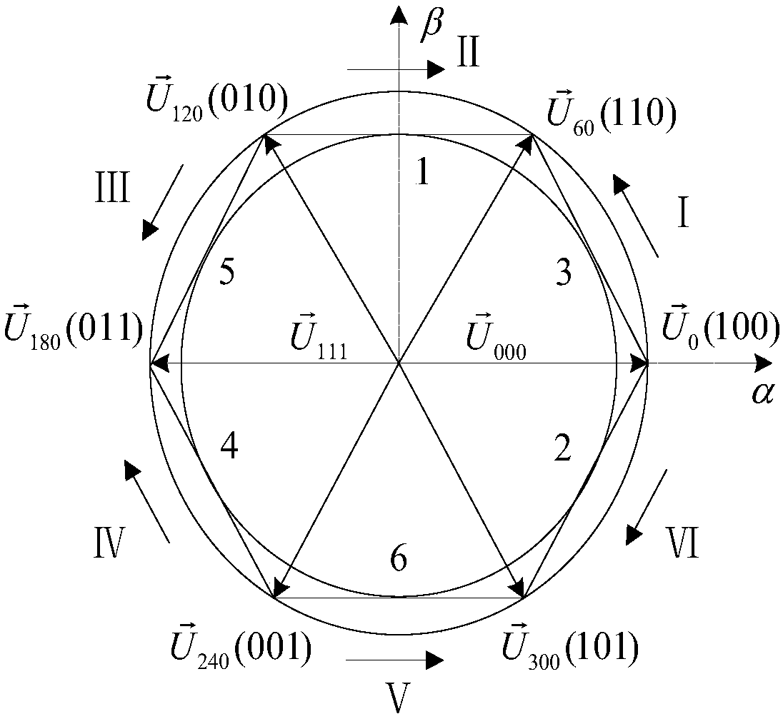
[0034] A: see figure 1Establish a mathematical model of a two-level grid-connected inverter. V1 to V6 represent 6 switching tubes, among which V1, V3 and V5 are the switching tubes of the upper bridge arm, and the corresponding V4, V6 and V2 represent the switching tubes of the lower bridge arm, and V1 is turned on When V4 is turned off, it is represented by binary number 1, when V1 is turned off, V4 is turned on by binary number 0, V3 and V6, V5 and V2 are the same, that is, the switching status of the upper bridge arm and the lower bridge arm is represented by the 3-digit binary number ABC , defining the switch state S x (x=A,B,C), see figure 2 As shown, there are 8 configurations of the three-way inverter bridge of the inverter. For different swit...


PUM


Abstract

The invention discloses a grid-connected inverter control method combining SVPWM with a sliding mode variable structure. The method comprises the following steps: A: establishing a two-level grid-connected inverter mathematical model, and obtaining a differential expression of output current of the inverter; B: deriving a corresponding state space equation based on the differential expression of the current, selecting d-axis and p-axis sliding modes output by an appropriate sliding mode inverter, and using the state space equation as a part of a sliding model current control objective function; and C: achieving current uncoupled control by current feedforward decoupling to reduce the corresponding control deviation. The grid-connected inverter control method disclosed by the invention hasthe advantages of having good dynamic steady state performance, being able to ensure relatively low switching frequency and completely meet the grid connection requirements, having good practicability, realizing the current uncoupled control by the current feedforward decoupling to reduce the corresponding control deviation, and having high tracking precision, low switching loss and easy digitization, etc.

Description

technical field [0001] The invention relates to a control method for a grid-connected inverter combining SVPWM and sliding mode variable structure. Background technique [0002] The continuous increase in demand for energy worldwide has promoted the development of megawatt-level renewable energy power generation systems. SVPWM is a relatively new control method developed in recent years. It is composed of six power switching elements of a three-phase power inverter. The pulse width modulation wave generated by the specific switching mode can make the output current waveform as close as possible to the ideal sinusoidal waveform. The space voltage vector PWM is different from the traditional sinusoidal PWM. It starts from the overall effect of the three-phase output voltage and focuses on Regarding how to obtain an ideal circular flux trajectory, compared with SPWM, SVPWM technology has a smaller harmonic component of the winding current waveform, and the rotating magnetic fie...

Claims


Application Information

Patent Timeline
Patent Type & Authority Applications(China)
IPC IPC(8): H02M7/48H02J3/38
CPCH02M7/48H02J3/38
Inventor 林火煅胡钦俊陈杰沈滨张志林孙嫱薛骅淳陈永松郑艺兵林财德黄靖林永翔陈跃彬
Owner ZHANGZHOU POWER SUPPLY COMPANY STATE GRID FUJIANELECTRIC POWER
Why Eureka
Try Eureka