Solid-liquid separation equipment using inertial mixed flow mode

A solid-liquid separation and mixed-flow technology, applied in the industrial field, can solve problems such as user trouble, inconvenient use, and complex structure, and achieve the effects of alleviating the use of raw materials, reducing the cost of use, and effectively utilizing

Inactive Publication Date: 2019-04-12
ANHUI PUSHI ECOLOGICAL ENVIRONMENT ENG
View PDF3 Cites 0 Cited by
  • Summary
  • Abstract
  • Description
  • Claims
  • Application Information

AI Technical Summary

Problems solved by technology

[0003] Traditional sewage treatment equipment has complex structure, inconvenient use, and insufficient separation, which brings great trouble to users, and cannot realize the three-level multi-level solid-liquid separation of industrial sewage according to the needs of use, and cannot Guarantee the thorough and efficient solid-liquid separation of sewage, which virtually increases the workload of personnel. It cannot meet the discharge requirements of industrial sewage, and the treatment efficiency of industrial sewage is low.

Method used


Image

  • Solid-liquid separation equipment using inertial mixed flow mode
  • Solid-liquid separation equipment using inertial mixed flow mode
  • Solid-liquid separation equipment using inertial mixed flow mode

Examples


Embodiment 1

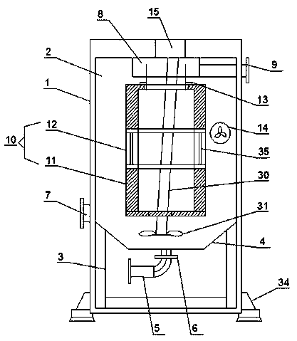
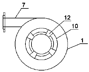
[0027] Such as Figure 1-4 As shown, the solid-liquid separation equipment using inertial mixed flow according to the embodiment of the present invention includes a water tank 1, and the water tank 1 is provided with a separation chamber 2 and a water inlet chamber 3 from top to bottom, and the separation chamber 2 and the A dividing plate 4 is arranged between the water inlet chambers 3, the section of the dividing plate 4 is a trapezoidal structure, and a return pipe 5 is arranged in the middle of the top end in the water inlet chamber 3, and the top end of the return pipe 5 penetrates through the partition. plate 4 and extends into the separation chamber 2, and the return pipe 5 is provided with a control valve 6, one side of the water tank 1 is provided with a water inlet pipe 7, and one side of the water inlet pipe 7 extends the In the separation chamber 2 and at the top side of the partition 4, the top in the separation chamber 2 is provided with a drainage groove 8, and...

Embodiment 2

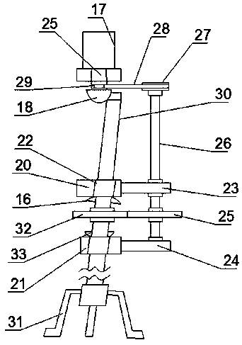
[0030] Such as Figure 3-4 As shown, the vortex mechanism 15 includes a drive motor 17 located on the top inner wall of the water tank 1, the output end of the drive motor 17 penetrates the cylinder 11 and extends to the bottom end of the separation chamber 2. Shaped rotating shaft 18, one side of the L-shaped rotating shaft 18 and a side plate 19 is arranged in the inner wall of the water tank 1, and a limit plate is symmetrically arranged on one side of the side plate 19 and located below the L-shaped rotating shaft 18 One 20 and limiting plate two 21, the bottom ends of said limiting plate one 20 and said limiting plate two 21 are all provided with holes 22, said limiting plate one 20 and said limiting plate two 21 One side is respectively provided with connecting rod one 23 and connecting rod two 24, and between said connecting rod one 23 and said connecting rod two 24, a gear plate 25 is arranged, and the bottom end of said gear plate 25 is connected with said connecting ...

Embodiment 3

[0032] Such as Figure 1-4As shown, a rolling ball 16 matching the hole 22 of the limiting plate 20 is provided above the gear tooth 1 32, the rolling ball 16 is a semicircular structure, and the bottom end of the water tank 1 There are several evenly distributed feet 34 . Further, the gear plate 25 is connected to the connecting rod 2 24 through a bearing 1, and a bearing 2 is provided at the intersection of the rotating shaft 2 26 and the connecting rod 1 23, and the water inlet tank 12 is provided with Filter screen 35, the aperture of described filter screen 35 is 0.2mm, and described water inlet pipe 7 and described water outlet pipe 9 are all provided with control valve two, and the pushing flow direction of described swirl propeller 14 is clockwise. flow.

[0033] Working principle: During normal operation, the solid-liquid mixture enters the bottom of the equipment from the water inlet pipe and forms a swirling flow. The inertial separation mechanism is fixed inside...


PUM


Abstract

The invention discloses solid-liquid separation equipment using an inertial mixed flow mode. The equipment comprises a water tank, the water tank is sequentially provided with a separation chamber anda water inlet chamber from top to bottom, a partition plate is arranged between the separation chamber and the water inlet chamber, and the cross section of the partition plate is of a trapezoidal structure; a return pipe is arranged in the middle of the top end in the water inlet chamber, the top end of the return pipe penetrates through the partition plate and extends into the separation chamber, and the return pipe is sleeved with a control valve; one side of the water tank is provided with a water inlet pipe, one end of the water inlet pipe extends into the separation chamber and is located at one side of the top of the partition plate, the top end in the separation chamber is provided with a drainage trough, one side of the drainage trough is provided with a water outlet pipe, and the side, away from the drainage trough, of the water outlet pipe extends to one side of the water tank. The solid-liquid separation equipment has the advantages that a solid phase and a liquid phase are separated, the liquid phase passing through an inertial separation mechanism axially moves upwards to enter a circular water outlet weir trough and is finally discharged from the water outlet pipeline, the use of a material can be alleviated to the great degree, the use cost is reduced, and therefore solid particles are effectively utilized.

Description

technical field [0001] The invention relates to the field of industrial technology, in particular to a solid-liquid separation device using inertia mixed flow. Background technique [0002] Industry refers to the work and process of collecting raw materials and processing them into products. In the process of industrial development, a large amount of sewage is often produced, and the sewage cannot be directly discharged into the river. It is necessary to use external devices to discharge the sewage Purification, and before purification, it is necessary to use solid-liquid separation equipment to separate the solids in the sewage, so that a solid-liquid separation equipment using inertial mixed flow has been developed. [0003] Traditional sewage treatment equipment has complex structure, inconvenient use, and insufficient separation, which brings great trouble to users, and cannot realize the three-level multi-level solid-liquid separation of industrial sewage according to...

Claims


Application Information

Patent Timeline
Patent Type & Authority Applications(China)
IPC IPC(8): B01D36/04
CPCB01D36/045
Inventor 张令金爽张锋
Owner ANHUI PUSHI ECOLOGICAL ENVIRONMENT ENG
Why Eureka
Try Eureka