Eureka AIR delivers breakthrough ideas for toughest innovation challenges, trusted by R&D personnel around the world.

A reforming reactor and its application

A technology for reforming reactors and reactors, applied in chemical instruments and methods, chemical/physical processes, etc., can solve the problems of reducing reactor height and waste of head space, etc., to improve reasonable distribution and solve waste of head space Larger, height-reducing effect

Active Publication Date: 2021-10-22
SHANGHAI HOTO PETROCHEM ENG
View PDF7 Cites 0 Cited by
  • Summary
  • Abstract
  • Description
  • Claims
  • Application Information

AI Technical Summary

Problems solved by technology

[0006] The purpose of the present invention is to provide a side-entry and top-out continuous reforming reactor and its application in order to overcome the defects in the above-mentioned prior art. While ensuring that the reaction materials are evenly distributed above and below the catalyst bed, the height of the reactor is effectively reduced, and the problem of wasting a large amount of space at the top of the reactor is solved. The hydrogen stripping of the catalyst collection bucket and the optimization of the whereabouts of hydrogen are adjusted to adjust different reactions. H in the device 2 / HC molar ratio, fully promote the main reaction and inhibit the side reaction, reduce investment and improve economic benefits

Method used


Image

  • A reforming reactor and its application
  • A reforming reactor and its application
  • A reforming reactor and its application

Examples


Embodiment 1

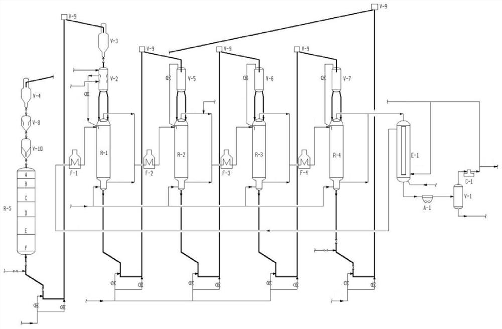
[0058] further reference figure 1 Describe in detail.

[0059] A catalytic reforming unit for refined gasoline (distillation range 80°C-175°C) includes a reaction section and a regeneration section, the reaction section consists of a first reforming reactor R-1, a second reforming reactor R-1, and a second reforming reactor operated in series. The reactor R-2, the third reforming reactor R-3, and the final reforming reactor R-4 are composed of four reactors, and the regeneration part includes the step I of catalyst burning (two-stage burning), using Step II for oxidation with chlorine to redisperse precious metal crystallites, and step III for reduction with hydrogen before being able to reduce the catalyst before it is reintroduced into the reactor.

[0060] The reaction part is in figure 1 In the middle, the first reforming reactor R-1, the second reforming reactor R-2, the third reforming reactor R-3, and the final reforming reactor R-4 are presented in a "side-by-side" c...

Embodiment 2

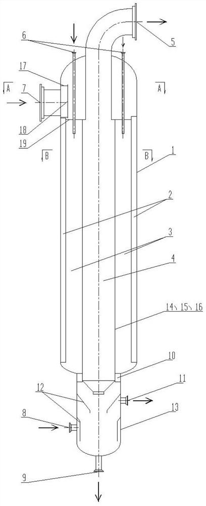
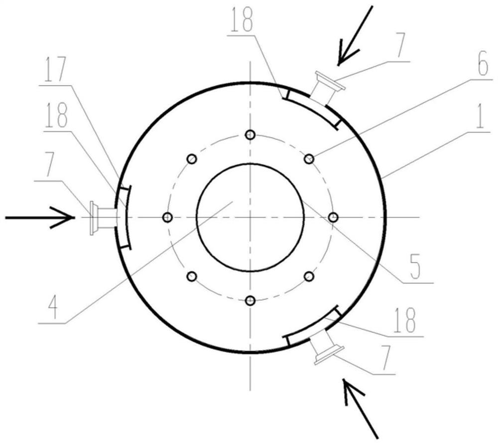
[0078] A reforming reactor, its structure is as Figure 2-4 As shown, the reforming reactor used adopts a radial bed structure, including a cylinder 1 , an upper head, a lower head, and a catalyst collection hopper 13 and other components. The upper head and the lower head are respectively arranged at both ends of the cylinder body 1, and are fixedly connected with the cylinder body to form a sealed structure, and the catalyst collecting bucket 13 is located under the lower head. The upper head used is spherical or ellipsoidal, and the corresponding shape or structure can be selected arbitrarily according to the actual situation. The top is provided with a reaction product outlet 5 and a catalyst feed pipe. The end of the catalyst feed pipe located outside the cylinder body 1 is the catalyst inlet 6, and the reaction product outlet 5 communicates with the central cylinder 4. The catalyst feed pipes are evenly distributed along the circumference, and the number set in this emb...

Embodiment 3

[0090] A reforming reactor, its structure is as figure 2 As shown, the reforming reactor used adopts a radial bed structure, including a cylinder 1 , an upper head, a lower head, and a catalyst collection hopper 13 and other components. The upper head and the lower head are respectively arranged at both ends of the cylinder body 1, and are fixedly connected with the cylinder body to form a sealed structure, and the catalyst collecting bucket 13 is located under the lower head. The upper head used is spherical or ellipsoidal, and the corresponding shape or structure can be selected arbitrarily according to the actual situation. The top is provided with a reaction product outlet 5 and a catalyst feed pipe. The end of the catalyst feed pipe located outside the cylinder body 1 is the catalyst inlet 6, and the reaction product outlet 5 communicates with the central cylinder 4. The catalyst feed pipes are evenly distributed along the circumference, and the number provided in this ...


PUM


Abstract

The invention relates to a reforming reactor and its application. By mixing hydrogen in stages and introducing lifting hydrogen and stripping hydrogen into different reactors, the H in the reforming reactor is reasonably adjusted. 2 / HC molar ratio, resulting in greatly improved aromatics and hydrogen yields compared to conventional prior art configurations. Compared with the prior art, the reforming reactor of the present invention adopts a radial reactor structure with side entry and ejection, which can effectively reduce the height of the reactor, solve the problem of waste of the top space of the reactor, and facilitate the central cylinder and For the inspection and maintenance of the fan-shaped cylinder, there is a catalyst collection bucket at the bottom of the reforming reactor, and hydrogen stripping is used. On the one hand, the hydrocarbon components carried on the catalyst can be stripped out, and at the same time, the lifting temperature of the catalyst is also reduced, which is conducive to safe operation and follow-up Material selection for equipment and pipelines.

Description

technical field [0001] The invention relates to the technical field of catalytic reforming, in particular to a reforming reactor and its application. Background technique [0002] The objective of the catalytic reformer is to convert naphthenes and paraffins (n-paraffins and iso-paraffins) into aromatics. The main reactions involved are naphthene dehydrogenation, alkane dehydrocyclization to aromatics and possible isomerization, while side reactions such as hydrocracking, hydrogenolysis, aromatics dealkylation and coke formation may also occur. The goal of technological development is to promote the main reaction and suppress the side reaction. [0003] At present, the continuous reforming technologies that have been industrialized in the world mainly include the technology of UOP Company of the United States and the technology of Axens Company of France. In the continuous reforming unit of UOP Company, the reaction system generally adopts overlapping reactors, and the rea...

Claims


Application Information

Patent Timeline
Patent Type & Authority Patents(China)
IPC IPC(8): B01J8/02B01J8/04
CPCB01J8/0214B01J8/0278B01J8/0285B01J8/0442
Inventor 蔡明件王丁马成国张韩
Owner SHANGHAI HOTO PETROCHEM ENG
Why Eureka
Eureka Blog
Learn More