Chain assembling device and pin shaft assembling device and method

A technology for assembling devices and pin shafts, which is applied in the direction of metal chains, etc., can solve the problems of high labor cost, assembly dislocation, easy deviation and dislocation, etc., and achieve the effect of high assembly efficiency, convenient refueling, and increased firmness

Active Publication Date: 2019-04-12
厦门闻佳科技有限公司
View PDF6 Cites 1 Cited by
  • Summary
  • Abstract
  • Description
  • Claims
  • Application Information

AI Technical Summary

Problems solved by technology

In the process of manual truncation and assembly, it is very easy to have inaccurate truncation, weak assembly or dislocation of assembly. After manual assembly, the effect of shape uniformity, consistency, accuracy and other aspects is not good, and it is difficult to ensure the safety of the chain. quality, and the technical requirements for workers are very high during the truncation and assembly process, and the labor cost is also very high
A small number of manufacturers also use automated equipment for assembly, but they all use simple cutting and assembly methods. They just cut off the chain through equipment, and then measure the cut chain to the required length and transport it to the designated assembly place for assembly and processing. , so not only the cost of labor and equipment is high, but the current equipment is not stable enough to cut off, prone to deviation and misalignment, and easy to wear during the transportation process, which will lead to low product quality and work efficiency as a whole

Method used


Image

  • Chain assembling device and pin shaft assembling device and method
  • Chain assembling device and pin shaft assembling device and method
  • Chain assembling device and pin shaft assembling device and method

Examples


Embodiment Construction

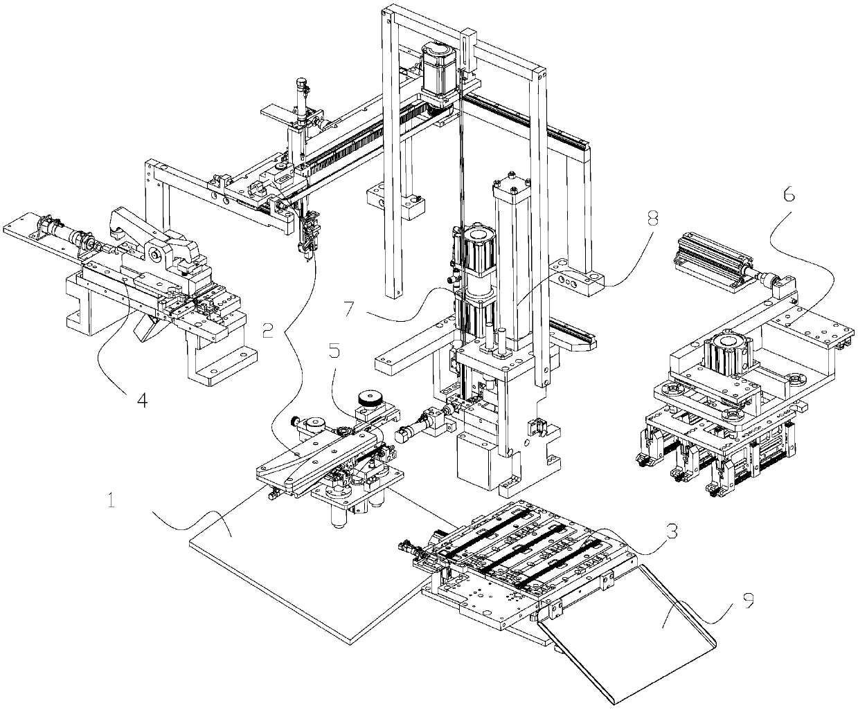
[0030] Such as figure 1 As shown, a chain assembly equipment includes a frame 1, a chain feeding and conveying device 2, a chain processing platform 3, a chain cutting device 4, a pin conveying device 5, a chain transfer device 6, a pin assembly device 7, Chain punching device 8. The chain feeding and conveying device 2 is arranged on the frame 1, and the chain feeding and conveying device 2 includes a chain feeding module and a chain conveying module. The chain conveying module is arranged on the frame 1 and above the chain feeding module. The chain conveying module is used to convey the chain on the chain feeding module to the chain processing platform 3. The chain processing platform 3 is arranged on the frame 1, and three stations are arranged on the chain processing platform 3, and the three stations include a first station 301, a second station 302 and a third station 303. The feeding end of the first station 301 is connected with the feeding end of the chain feeding mo...


PUM


Abstract

The invention relates to the field of intelligent manufacturing of chains and discloses a pin shaft assembling device. The device comprises a pin shaft assembling support, a pin shaft assembling lifting air cylinder, a pin shaft assembling moving frame, a pin shaft assembling matched block, a pin shaft assembly base, a pin shaft piece feeding air cylinder, a pin shaft piece material push rod and apin shaft piece containing frame. The fixed part of the pin shaft assembling lifting air cylinder is arranged on the pin shaft assembling support, and the movable part of the pin shaft assembling lifting air cylinder is fixedly connected with the top of the pin shaft assembling moving frame. A pin shaft assembling pressing block is arranged below a pin shaft assembling positioning rod, and the pin shaft assembling pressing block is arranged on the pin shaft assembly base. The pin shaft piece material push rod is arranged in a movable matched groove and is matched with the pin shaft assembly base. The pin shaft assembling device has the beneficial effects that the pin shaft assembling device is arranged so that a pin shaft piece can be directly assembled with a pin shaft, the pin shaft piece can be positioned accurately, the assembling firmness of the pin shaft piece and the pin shaft is increased, pin shaft piece replacing is convenient, and the assembling efficiency is high.

Description

Technical field [0001] The invention relates to the field of intelligent chain manufacturing, in particular to a pin assembly device and method and fully automatic cutting assembly equipment. Background technique [0002] In modern industrial manufacturing, many complicated machines are assembled by humans, including mobile phones and computers in the electronics industry, as well as automobile manufacturing and other household appliances. In these industrial manufacturing, many small assembly steps are required to be combined together, especially the cutting and assembly of the chain, which are manually cut off the pin piece with a cutting tool, and then the pin is removed, and the required length is measured before taking the new one. The pin shaft and the pin shaft piece are assembled on the pin shaft by an assembly tool to connect the specified length of the chain. In the process of manual truncation and assembly, it is very prone to inaccurate truncation, poor assembly, or ...

Claims


Application Information

Patent Timeline
Patent Type & Authority Applications(China)
IPC IPC(8): B21L9/06
CPCB21L9/065
Inventor 桑军军
Owner 厦门闻佳科技有限公司
Why Eureka
Try Eureka