Continuous casting ladle turret hydraulic slip ring installing apparatus and method

A technology for hydraulic slip rings and installation devices, which is applied to casting equipment, casting molten material containers, metal processing equipment, etc., which can solve the problems of low installation accuracy, complicated operation of slip rings, time-consuming disassembly of slip rings, etc., and improve installation The effect of precision

Active Publication Date: 2019-04-12
CHINA MCC17 GRP
View PDF6 Cites 2 Cited by
  • Summary
  • Abstract
  • Description
  • Claims
  • Application Information

AI Technical Summary

Problems solved by technology

[0002] At present, slip rings need to be installed during use. The installation of existing slip rings is complex and cannot be fixed quickly. During maintenance, it takes a lot of time to disassemble the slip ring, which directly affects work efficiency. The surface of the slip ring is in contact with air, not only A lot of dust will fall on the surface, which will cause the slip ring to dissipate heat slowly, and the surface of the material is prone to rust. If the rusted parts are not cleaned in time, the entire slip ring will be slowly corroded and the slip ring will be scrapped. In addition, hydraulic slip rings and electrical slip rings The ring will cause relative rotation during the installation process, resulting in low installation accuracy, so it is imminent to create a hydraulic slip ring installation device and method for the continuous casting ladle turret

Method used


Image

  • Continuous casting ladle turret hydraulic slip ring installing apparatus and method
  • Continuous casting ladle turret hydraulic slip ring installing apparatus and method

Examples


Embodiment Construction

[0023] In order to make the object, technical solution and advantages of the present invention clearer, the present invention will be further described in detail below in conjunction with the accompanying drawings and embodiments. It should be understood that the specific embodiments described here are only used to explain the present invention, not to limit the present invention.

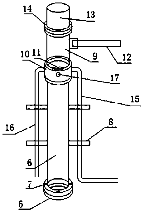
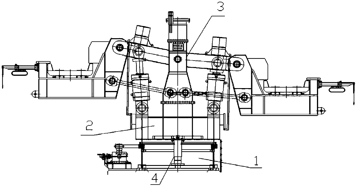
[0024] see Figure 1-2 As shown, the hydraulic slip ring installation device of the continuous casting ladle turret of this embodiment includes a slip ring assembly, a rotator 2 and a base 1, and the slip ring assembly includes a fixed seat base 5, a fixed seat 6, connecting bolts I7, Medium support 8, hydraulic slip ring rotating body 9, slip ring fixing seat 10, connecting bolt II11, electrical slip ring 13, connecting bolt III14, hydraulic inlet pipeline 15, hydraulic outlet pipeline 16, the upper end of the fixing seat base 5 is connected The bolt I7 is fixedly connected with a fixed seat 6, a...


PUM

PropertyMeasurementUnit
heightaaaaaaaaaa
heightaaaaaaaaaa

Abstract

The invention discloses a continuous casting ladle turret hydraulic slip ring installing apparatus and method, and relates to the technical field of metallurgical industry continuous casting machine devices. The continuous casting ladle turret hydraulic slip ring installing apparatus comprises a slip ring assembly, a revolving body and a pedestal. The slip ring assembly comprises a fixing seat pedestal, a fixing seat, a connecting bolt I, a medium supporting frame, a hydraulic slip ring rotating body, a slip ring fixing seat, a connecting bolt II, an electric slip ring, a connecting bolt III,a hydraulic inlet pipeline and a hydraulic outlet pipeline. According to the continuous casting ladle turret hydraulic slip ring installing apparatus and method, the fixing seat is firstly removed when the pedestal of a ladle turret is installed to ensure that the slip ring assembly is not damaged when the pedestal of the ladle turret is hoisted; after the revolving body is hoisted, the fixing seat is firstly installed, and then vertical alignment is conducted by using a laser collimator; then the hydraulic slip ring and the electric slip ring are installed in sequence; finally, a hydraulic wire and an electric wire are connected, and the hydraulic slip ring and the inner part of the revolving body are connected into a whole; and through the procedures, installing efficiency of the whole apparatus is ensured, and installing precision is increased.

Description

technical field [0001] The invention relates to the technical field of continuous casting machine equipment in the metallurgical industry, and more specifically relates to a hydraulic slip ring installation device and method for a continuous casting ladle turret. Background technique [0002] At present, slip rings need to be installed during use. The installation of existing slip rings is complex and cannot be fixed quickly. During maintenance, it takes a lot of time to disassemble the slip ring, which directly affects work efficiency. The surface of the slip ring is in contact with air, not only There will be a lot of dust on the surface, which will cause the slip ring to dissipate heat slowly, and the surface of the material is prone to rust. If the rusted parts are not cleaned in time, the entire slip ring will be slowly corroded and the slip ring will be scrapped. In addition, hydraulic slip rings and electrical slip rings The ring will cause relative rotation during th...

Claims


Application Information

Patent Timeline
Patent Type & Authority Applications(China)
IPC IPC(8): B22D41/13
CPCB22D41/13
Inventor 孔炯郭建华朱红刚杨静陈志翁勇荣张俊郑治飞周军号
Owner CHINA MCC17 GRP
Why Eureka
Try Eureka