Ionic exchange membrane electrolytic cell device and system and method of electrolytic etching waste liquid

A technology of ionic membrane electrolyzer and etching waste liquid, which is applied in the direction of electrolysis process, electrolysis components, process efficiency improvement, etc. It can solve the problems of electrolyzer work influence, easy fatigue, accidents, etc., and achieve the reduction of work risk factor, Less fatigue and longer service life

Pending Publication Date: 2018-09-04
深圳市恒宝源环保科技有限公司
View PDF8 Cites 2 Cited by
  • Summary
  • Abstract
  • Description
  • Claims
  • Application Information

AI Technical Summary

Problems solved by technology

However, at present, the staff is holding the operation, and continuously detects between multiple plates in a short period of time, which is prone to fatigue, and it is easy to cause the current clamp to touch the adjacent plates, which will affect the work of the electrolytic cell, and may even cause an accident

Method used


Image

  • Ionic exchange membrane electrolytic cell device and system and method of electrolytic etching waste liquid
  • Ionic exchange membrane electrolytic cell device and system and method of electrolytic etching waste liquid
  • Ionic exchange membrane electrolytic cell device and system and method of electrolytic etching waste liquid

Examples


Embodiment Construction

[0057] In the following specific description, many specific details are set forth in order to fully understand the present invention, but the present invention can also be implemented in other ways different from this description, therefore, the protection scope of the present invention is not limited by the specific implementation disclosed below. Example limitations.

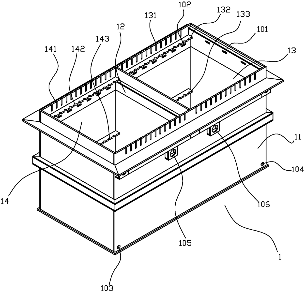
[0058] Such as figure 1 As shown, a kind of ionic membrane electrolyzer device 1 of the present invention, comprises the tank body 11 that opening faces upwards, is provided with the anticorrosion plastic mold frame 12 of vertical direction in the cavity of tank body 11, and plastic mold frame 12 is provided with ion Membrane, the ionic membrane separates the cavity into a cathode area 13 and an anode area 14, and the cathode area 13 is provided with several vertical cathode plates; the anode area 14 is provided with several vertical anode plates, and the cathode area 13 both sides The upper edge of the catho...


PUM


Abstract

The invention discloses an ionic exchange membrane electrolytic cell device. The ionic exchange membrane cell device comprises a slot body with an opening upwards, an cavity of the slot body is internally provided with an anti-corrosion plastic mold frame and an ionic membrane which are arranged in the vertical direction, and the cavity is separated by the ionic membrane into a cathode area and ananode area. The cathode area is provided with a plurality of cathode plates, cathode upper clamping openings are formed in the upper edges of two sides of the cathode area, cathode side clamping openings are formed in the side wall of the cathode area, cathode bottom clamping openings are formed in the bottom of the cathode area, and cathode guide clamping openings extending inwards are further formed in the upper edges of the two sides of the cathode area. The anode area is provided with an anode plate, anode upper clamping openings are formed in the upper edges of two sides of the anode area, anode side clamping openings are formed in the side wall of the anode area, anode bottom clamping openings are formed in the bottom of the anode area, and anode guide clamping openings extending inwards are further formed in the upper edges of the two sides of the anode area. Based on the technical characteristics of arranging the upper clamping openings on the upper edges of the slot body, theside clamping openings on the side walls, the bottom clamping openings at the bottom, the guide clamping openings corresponding to the upper clamping openings and extending inwards on the upper edgesof two sides of the slot body, in the process of installing pole plates, the positioning is accurate, installation is convenient, and the installation efficiency is significantly improved.

Description

technical field [0001] The invention relates to the electrolysis technology of etching waste liquid, in particular to an ion membrane electrolyzer device and a system and method for electrolyzing etching waste liquid. Background technique [0002] At present, in the existing electrolytic treatment device for etching waste liquid, the initial installation and the installation process of the electrode plate after the copper extraction operation in the working process all need to be completed manually by the operator, including visual alignment and assembly positioning. However, during this installation operation, the electrode plate has no guiding function when it is assembled downwards, resulting in easy deviation and misalignment of the installation, which increases the installation time, especially when copper is to be lifted during the electrolysis process, which will affect the production of the electrolysis efficiency. [0003] In addition, when the electrolyzer is work...

Claims


Application Information

Patent Timeline
Patent Type & Authority Applications(China)
IPC IPC(8): C25C1/12C25C7/00C23F1/46C25C7/06
CPCC23F1/46C25C1/12C25C7/00C25C7/06Y02P10/20
Inventor 余子亿
Owner 深圳市恒宝源环保科技有限公司
Why Eureka
Try Eureka