Automatic discharging machine

A technology of automatic unloading and unloading machine, which is applied in the direction of conveyor, loading/unloading, conveyor objects, etc., to achieve the effect of not easy to deviate, improve the degree of automation, and stabilize the unloading

Inactive Publication Date: 2019-04-12
常州钟楼高新技术创业服务有限公司
View PDF1 Cites 1 Cited by
  • Summary
  • Abstract
  • Description
  • Claims
  • Application Information

AI Technical Summary

Problems solved by technology

[0004] But the disadvantage of the above-mentioned unloading device is that the device needs staff to operate on the side during the process of stacking materials. After the materials are stacked to a certain height, the staff turns off the pitching telescopic belt conveyor, and then The control bracket walks on the rails. Since the stockpiling is generally selected in an open open space, in hot weather, the staff operates the unloading device to move outside, which is very hard and brings a certain workload to the staff.

Method used


Image

  • Automatic discharging machine
  • Automatic discharging machine
  • Automatic discharging machine

Examples


Embodiment 1

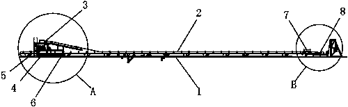
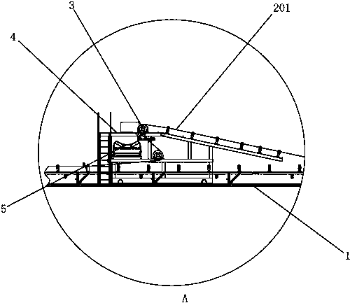
[0024] Embodiment 1: a kind of automatic unloading machine, as Figure 1 to Figure 4 As shown, it includes a frame 1 and a support 4 arranged on the top of the frame 1. The frame 1 selects a gantry frame extending horizontally along the left and right directions, and the support 4 extends horizontally along the front and rear directions. Transport to the first transport mechanism 2 on the support 4. In this embodiment, the first transport mechanism 2 includes a first conveyor belt 201 arranged horizontally along the length direction of the frame 1 and a first drive for driving the first conveyor belt 201 to transport materials. Components, the first drive part is the first drive motor, the first drive motor works, drives the first conveyor belt 201 to transport the material from the right end of the frame 1 to the left end, and the first conveyor belt 201 discharges the material in the middle of the frame 1 At one end, a discharge roller 3 is arranged on the upper end of the s...

Embodiment 2

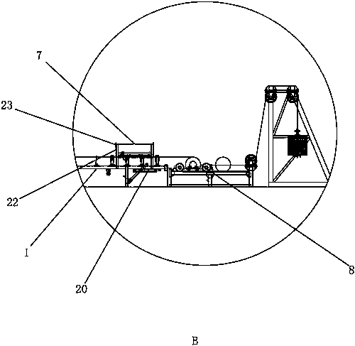
[0031] Embodiment 2: a kind of automatic unloading machine, differs from embodiment 1 in that, as Figure 4 As shown, the support 4 includes a sliding frame 21 extending along the feeding direction of the second conveyor belt 12, the sliding frame 21 slides on the support 4 along the feeding direction of the second conveyor belt 12, and the second conveying mechanism is arranged on the sliding On the shifting frame 21, the second conveying mechanism can be moved to the left or right by the sliding frame 21, thereby increasing the conveying stroke of the material on the second conveyor belt 12, so that the position where the material is stacked is far enough away from the frame 1 to reach The stacking effect is better.

Embodiment 3

[0032] Embodiment 3: a kind of automatic unloading machine, the difference with embodiment 6 is, as Figure 6 As shown, on the basis of Embodiment 1, a blower blowing along the extension direction of the second conveyer belt 12 is arranged in the bin body 9, and the blower is arranged at one end of the bin body 9, and is arranged on the bin body 9 at the opposite end. Ventilation hole is arranged, and filter screen 19 is arranged on the ventilation hole, and the wind power of blower is less, can blow the dust in the material to ventilation hole, fly out from the mesh of filter screen 19 then, and material normally falls downwards, filter Net 19 can prevent a little material from flying out from the air vent, and plays the effect of removing dust.


PUM


Abstract

The invention discloses an automatic discharging machine. The automatic discharging machine comprises a machine frame and a support arranged above the machine frame, the machine frame is provided witha first conveying mechanism and a sliding driving part, wherein the first conveying mechanism is used for conveying materials to the support, and the sliding driving part is used for driving the support to slide along the material conveying direction of the first conveying mechanism on the machine frame; a telescopic mechanism extending outwards from the two sides of the machine frame is arrangedon the support, and the telescopic mechanism is provided with an induction detection assembly for detecting the stacking height of the materials so as to control the support to slide on the machine frame. According to the machine, the support is automatically controlled to automatically move on the machine frame, manual operation is not needed, so that a certain working load is relieved for workers; and meanwhile, the automation degree of the automatic discharging machine is improved.

Description

technical field [0001] The invention relates to an unloading device, in particular to an automatic unloading machine. Background technique [0002] At present, in the accumulation process of small granular bulk materials, especially in the accumulation process of rice, rice and other grains, belt conveyors are commonly used. The characteristics of belt conveyors are that the height of accumulated bulk materials is low and cannot be adjusted. The direction of the bulk material is single, the coordination with the large unloading vehicle is poor, and the mobility of the equipment is poor; [0003] In a Chinese patent document with the patent application number "201110203037.0", a mobile pitching telescopic unloading device is described. Install a roller, the roller can walk on the rails of the dormitory road, the winch is installed on the bracket, and the motor installed on the conveyor belt drives the wheel so that the conveyor belt and the bracket, the herringbone distribut...

Claims


Application Information

Patent Timeline
Patent Type & Authority Applications(China)
IPC IPC(8): B65G65/00B65G47/20
CPCB65G65/005B65G47/20B65G2201/042
Inventor 吴晗
Owner 常州钟楼高新技术创业服务有限公司
Why Eureka
Try Eureka