Eddy current axial damper

A damper, eddy current technology, applied in springs/shock absorbers, springs, magnetic springs, etc., can solve the problems of size interference, enlarged magnet frame size, difficulties in design, production and assembly, and reduce the cost of life. , The effect of reducing the whole life cost

Active Publication Date: 2019-04-12
湖南省潇振工程科技有限公司
View PDF7 Cites 5 Cited by
  • Summary
  • Abstract
  • Description
  • Claims
  • Application Information

AI Technical Summary

Problems solved by technology

[0003] In the existing eddy current axial damper, the part that generates eddy current damping is coupled with the transmission member, and the dimensions between the two are interfered with each other (for example, when more magnets are required, it will be limited by the length of the nut, when When using a larger-sized transmission component, the size of the magnet frame will also increase accordingly; it is difficult to meet the demand for a larger damping force in a smaller-sized eddy current axial damper), which brings new problems to design, production and assembly. many difficulties

Method used


Image

  • Eddy current axial damper
  • Eddy current axial damper
  • Eddy current axial damper

Examples


Embodiment 1

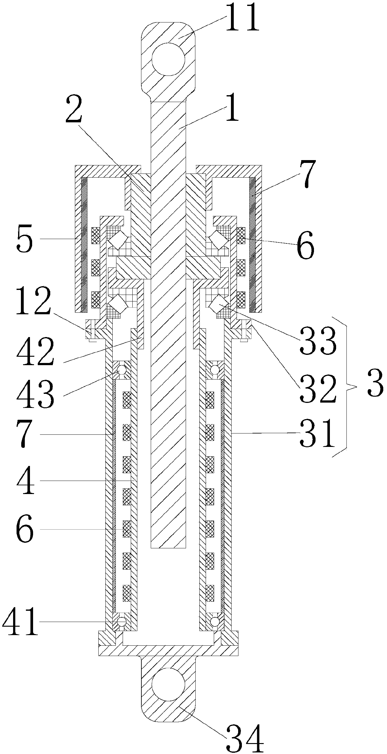
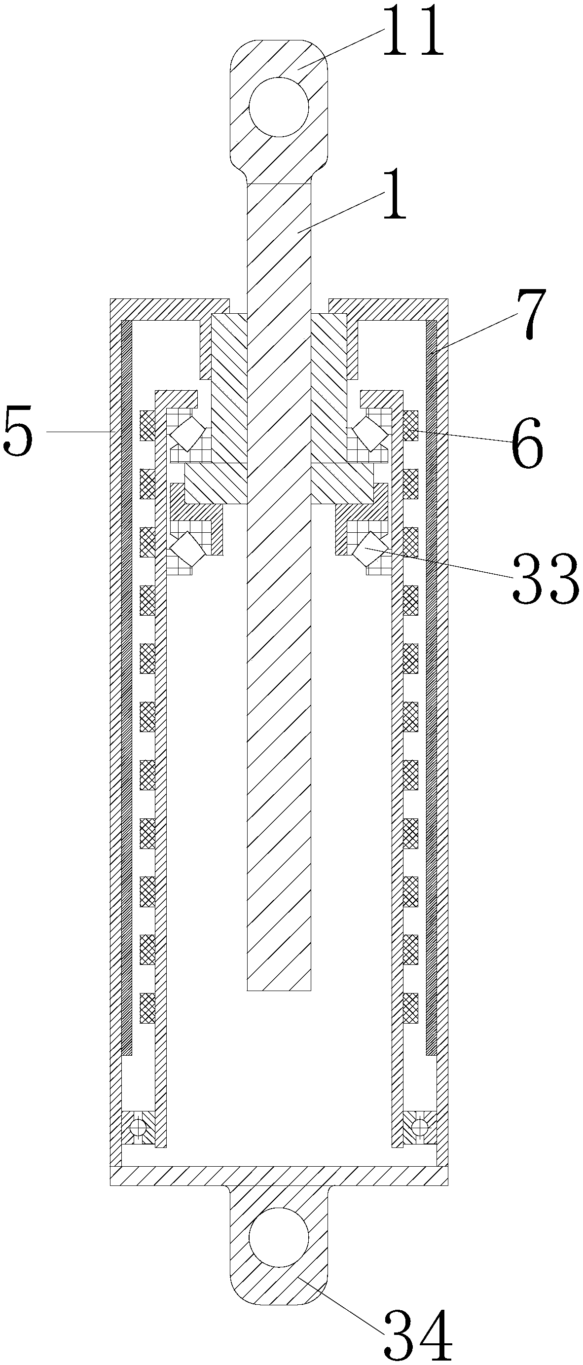
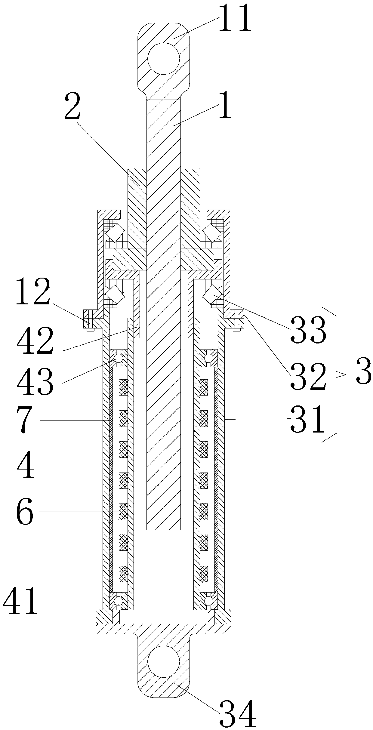
[0036] Such as Figure 1-3 Shown, a kind of electric eddy current axial damper described in the present invention comprises:

[0037] Screw rod 1 and nut 2 adapted thereto;

[0038] A fixed cylinder 3 made of a magnetically conductive material is sleeved on the outside of the screw 1;

[0039] The inner drum 4 made of magnetically permeable material is connected with the nut 2 and sleeved between the screw rod 1 and the fixed drum 3. Several magnets 6 are arranged on the periphery of the inner drum 4, corresponding to the inner drum 4. The inner wall of the fixed cylinder 3 is provided with a conductor pipe 7;

[0040] The outer drum 5 made of magnetically conductive material is connected to the nut 2 and sleeved on the outside of the fixed drum 3. The inner wall of the outer drum 5 is provided with a conductor tube 7, and the corresponding peripheral edge of the fixed drum 3 is provided with Several magnets 6.

[0041] As a preferred solution of this embodiment, the fixed...

Embodiment 2

[0047] Such as Figure 4 As shown, an eddy current axial damper according to the present invention, on the basis of Embodiment 1, the eddy current axial damper also includes a guiding inner tube 8 and a guiding outer tube 9 .

[0048] The guide inner tube 8 is connected to the fixed cylinder 3, the guide outer tube 9 is connected to the screw 1, one end of the guide inner tube 8 is sleeved on one end of the guide outer tube 9, and the guide The outer wall of the inner tube 8 is attached to the inner wall of the guide outer tube 9 and can slide relatively. The inner wall of the guide inner tube 8 is connected with at least one support ring 81 , and all the support rings 81 are connected to the outer wall of the fixed cylinder 3 .

[0049] With this structural setting, the damper needs to be made longer to achieve the maximum damping force and damping coefficient required by the design. When the damper is placed in a horizontal state, the deflection of the middle part of the dam...


PUM


Abstract

The invention discloses an eddy current axial damper. The eddy current axial damper comprises a screw, a nut, a fixed drum, an inner rotating drum and an outer rotating drum. The fixed drum sleeves the outer side of the screw. The inner rotating drum is connected with the nut and arranged between the screw and the fixed drum in a sleeving mode. Magnets are arranged on the periphery of the inner rotating drum, and a conductor pipe is arranged on the inner wall of the fixed drum. The outer rotating drum is connected with the nut and sleeves the outer side of the fixed drum. A conductor pipe is arranged on the inner wall of the outer rotating drum, and magnets are arranged on the periphery of the fixed drum. According to the eddy current axial damper, two sets of module connection are formedbetween the inner rotating drum and the fixed drum and between the outer rotating drum and the fixed drum, the sizes are not mutually affected, the parts can be independently designed, and modularizedproduction and combination are achieved. By means of multiple combination modes such as inner and outer rotation, inner rotation and outer rotation, the requirements for the damper size limitation, the damping force inertia force change mode and the heat dissipation efficiency are met. The structure comprises a movement conversion mechanism and an eddy current damping generator. The eddy currentdamping generator is free of the frictional loss, after the service life of the damper ends, only the movement conversion mechanism needs to be replaced, the eddy current damping generator can continue to be used, and therefore the life cycle cost is reduced.

Description

technical field [0001] The invention relates to the field of damping devices, in particular to an eddy current axial damper. Background technique [0002] The basic principle of eddy current damping is: when the conductor plate in the local magnetic field cuts the magnetic force line, an eddy current will be generated in the conductor plate, and the eddy current will generate a new magnetic field opposite to the direction of the original magnetic field, thus creating a gap between the original magnetic field and the conductor. It forms a damping force that hinders the relative movement of the two, and at the same time, the resistance effect of the conductor plate converts the kinetic energy obtained by the conductor plate into heat energy and dissipates it through eddy currents. If the conductor plate is connected with the vibrating structure, it can produce the effect of structural vibration reduction and energy consumption, and become an eddy current damper. Compared with...

Claims


Application Information

Patent Timeline
Patent Type & Authority Applications(China)
IPC IPC(8): F16F6/00
Inventor 陈政清华旭刚张弘毅牛华伟
Owner 湖南省潇振工程科技有限公司
Why Eureka
Try Eureka