Heat insulation pipe body

A technology for insulating pipes and pipe bodies, applied in the field of pipelines, can solve the problems of poor heat insulation effect, high replacement cost, easy deformation, etc., and achieve the effects of clear and convenient replacement of pipe bodies, convenient temperature influence, and increased service life.

Inactive Publication Date: 2019-04-12
乌兰察布中石油昆仑燃气有限公司
View PDF10 Cites 10 Cited by
  • Summary
  • Abstract
  • Description
  • Claims
  • Application Information

AI Technical Summary

Problems solved by technology

[0004] In order to solve the above problems, the conveying pipeline in the prior art generally has the conveying layer and the heat insulation layer integrated, and is easily deformed in the face of temperature changes. When the pipeline is damaged, the damaged end cannot be accurately known, and it can only be replaced as a whole. , very inconvenient, and the cost of replacement is very high. How to solve the problem that the pipe body can only transport one medium, the conveying pipe body is easily deformed by heat, the heat insulation effect is not good, and the damage cannot be stopped in time when the heat source is damaged, and the damage point cannot be clearly defined and damaged Afterwards, the overall replacement of the pipe body and other issues are the main problems that need to be solved at this stage.

Method used


Image

  • Heat insulation pipe body
  • Heat insulation pipe body
  • Heat insulation pipe body

Examples


Embodiment Construction

[0031] The specific embodiment of the present invention will be described in further detail below in conjunction with the form of the accompanying drawings, but the following examples only enumerate preferred embodiments, which only serve as an explanation to help understand the present invention, It should not be understood as limiting the present invention.

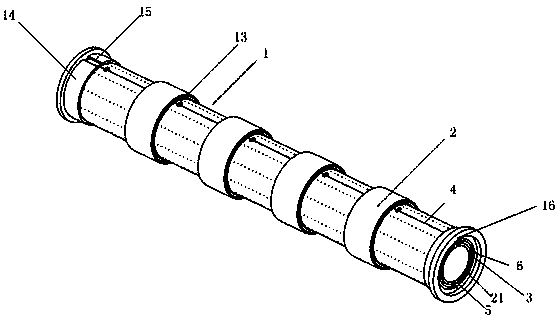
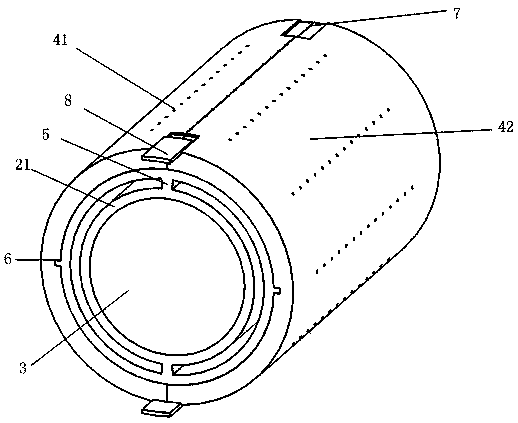
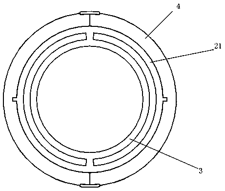
[0032] Such as Figure 1-8 A heat-insulating pipe body is shown, including a pipe body unit 1 and a connecting mechanism 2. The pipe body unit 1 includes an inner pipe 3, an intermediate pipe 21 and a heat-insulating single pipe 4. The inner pipe 3, the middle The tube 21 and the heat-insulating single tube 4 are sleeved sequentially from the inside to the outside; the inner tube 3 is a hollow pipe, and the outer wall of the inner tube 3 is axially provided with a support bar 5, and the outer wall of the inner tube 3 is Supported by the support bar 5 to form an annular gap channel with the intermediate pipe 21, the out...


PUM


Abstract

The invention discloses a heat insulation pipe body. The heat insulation pipe body comprises a pipe body single body and a connecting mechanism, wherein the pipe body single body comprises an inner pipe, a middle pipe and a heat insulation single pipe; the inner pipe, the middle pipe and the heat insulation single pipe are sequentially arranged from inside to outside in a sleeved mode; the heat insulation single pipe is a detachable pipe body and comprises a left heat insulation single pipe and a right heat insulation single pipe, and splicing grooves are both formed in the head end of the left heat insulation single pipe and the tail end of the right heat insulation single pipe; and a sliding splicing pressing block is arranged on the head end splicing groove, and a heat insulating cavitywith a circular-ring-shaped section is arranged in the heat insulation single pipe. According to the heat insulation pipe body, a multi-medium simultaneous conveying multi-layer heat insulation pipeis adopted, so that multiple purposes of one pipe can be realized; the detachable heat insulation single pipe is adopted, so that the disassembly is convenient, only the damaged needs to be disassembled and replaced, and the disassembly cost is saved; a heat insulation cavity separation reaction heat-reduction device is adopted, can be used for carrying out a preferential reaction on the differentheat environments when conveying is performed by the pipe body so that an object to be conveyed can be more conveniently prevented from being affected by the temperature; and moreover, the pipe bodycan be replaced more conveniently.

Description

technical field [0001] The invention relates to the technical field of pipes, in particular to a heat insulating pipe body. Background technique [0002] For flammable and explosive gases, high-purity gases, cold source gases, etc., in order to avoid loss and harm to the environment, non-destructive storage is often used for storage and transportation. High-vacuum multi-layer insulated cryogenic liquid pipelines have been widely used in the field of low-temperature storage and transportation due to their excellent thermal insulation performance, involving machinery, petrochemical, metallurgy, biology, medical, aerospace and many other industries. At present, the development and process research of domestic high-vacuum multi-layer heat insulation technology is on the rise, but the structure of the vacuum heat-insulated low-temperature pipeline still adopts the traditional two-layer structure, which has poor cold insulation effect and is prone to low temperature during transpo...

Claims


Application Information

Patent Timeline
IPC IPC(8): F16L59/02F16L59/06F16L51/02
CPCF16L51/025F16L59/024F16L59/06
Inventor 苏慧祎邱丽波巩华荣李波杨菊萍
Owner 乌兰察布中石油昆仑燃气有限公司
Why Eureka
Try Eureka