
Gas pipeline with reducing speed increase and anti-backflow blocking for gas water heater

A technology for gas water heaters and gas pipelines, which is applied to fluid heaters, lighting and heating equipment, and combustion methods. It can solve problems such as inability to heat immediately, inability to transport gas, and blockage of gas pipelines, and achieve the effect of accelerating the emission speed

Active Publication Date: 2019-04-12
河北任德管业有限公司
View PDF10 Cites 0 Cited by
  • Summary
  • Abstract
  • Description
  • Claims
  • Application Information

AI Technical Summary

Problems solved by technology

[0002] In the process of using a gas water heater, it is more common to encounter that the water in the water heater is not hot after turning on the switch. When the equipment has no apparent damage or obvious failure, it is usually where the gas pipeline is located. The pressure of the gas pipeline is low or the gas pipeline is blocked. One end of the gas pipeline is connected to the The combustion chambers are connected, because there are a small amount of impurities in the gas, and these substances will flow back into the combustion pipe after combustion, causing the gas pipe to be blocked and the gas cannot be transported. Moreover, the current gas pipes are straight-through pipes. Once the pressure of the gas is not enough, the speed of entry become extremely slow and cannot be heated immediately

Method used


Image

  • Gas pipeline with reducing speed increase and anti-backflow blocking for gas water heater
  • Gas pipeline with reducing speed increase and anti-backflow blocking for gas water heater
  • Gas pipeline with reducing speed increase and anti-backflow blocking for gas water heater

Examples


Embodiment

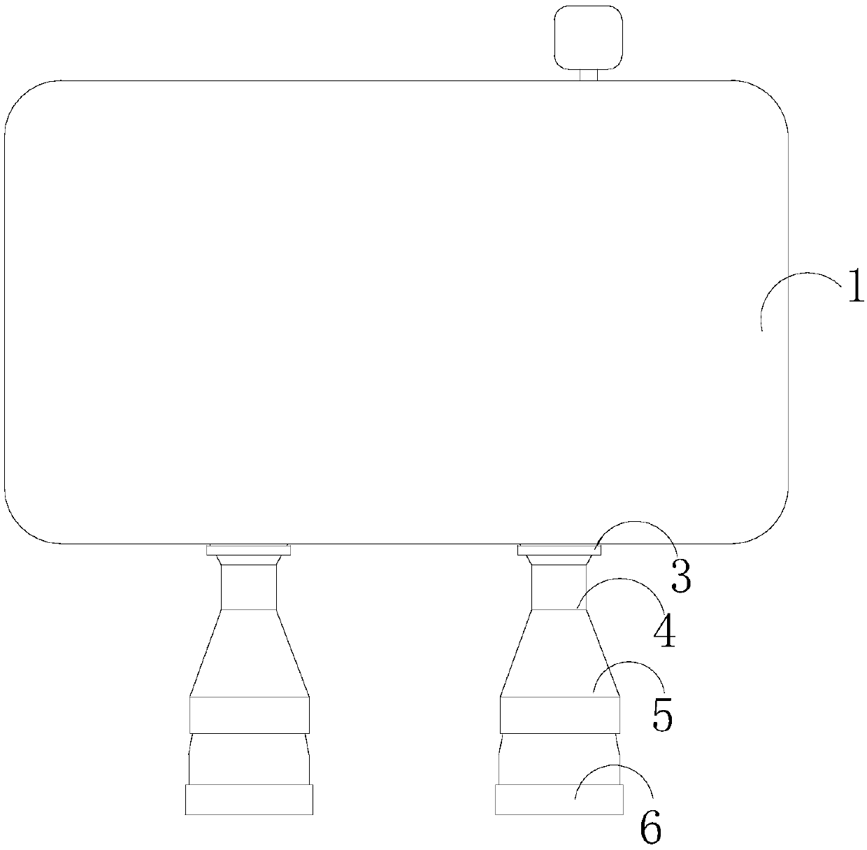
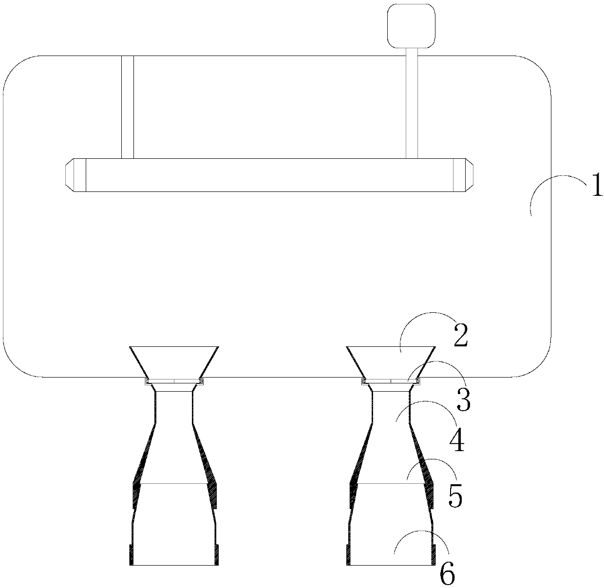
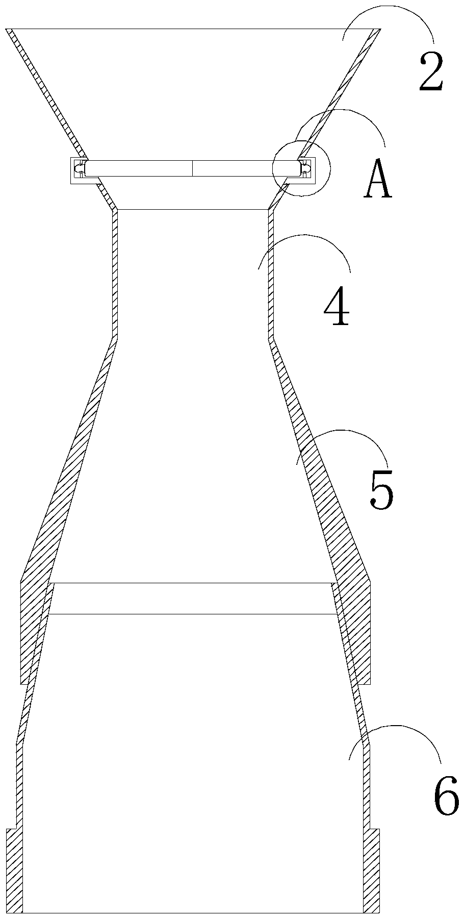
[0021] see Figure 1-Figure 6 , the present invention provides gas pipes for gas water heaters with variable diameters, increased speed and anti-reflux clogging. 4. Both horizontal ends are respectively connected to the diffuser tube 2 and the shrink tube 5. The diffuser tube 2 and the shrink tube 5 are both hollow structures. The height of the shrink tube 5 is smaller than that of the diffuser tube 2. The end of the diffuser tube 2 is located in the combustion chamber 1, a nozzle 6 is installed in the middle of the end of the shrink tube 5, and a stop structure 3 is installed on the diffuser tube 2 near the straight tube 4. The diffuser tube 2 and the shrink tube 5 are not mechanically connected to the straight tube 4. The diameter of one end is larger than that of the other end, and the three tubes of the diffuser tube 2, the straight tube 4 and the shrink tube 5 are on the same straight line and communicate with each other.

[0022] The flow-stopping structure 3 is provide...


PUM


Abstract

The invention discloses a gas pipeline with reducing speed increase and anti-backflow blocking for a gas water heater. The gas pipeline structurally comprises a combustion chamber, diffusion pipes, flow stopping structures, straight pipes, shrinkage pipes and nozzles. The two horizontal ends of each straight pipe are separately connected with the corresponding diffusion pipe and shrinkage pipe, and the diffusion pipes and the shrinkage pipes are of hollow structures. The height of the shrinkage pipes is smaller than that of the diffusion pipes, the tail ends of the diffusion pipes are locatedin the combustion chamber, and the nozzles are installed in the middle of the tail ends of the shrinkage pipes. The flow stopping structures are installed at the positions, close to the straight pipes, of the diffusion pipes. The diffusion pipes, the flow stopping structures and other structures cooperate together, the change of the diameter is used for increasing the speed of gas entering the combustion chamber, and the pipeline pressure being insufficient to transport the gas is avoided; and on the other hand, opening and closing of the flow stopping structures are automatically controlled according to the pressure difference, and the situation that the gas is unable to be transported due to backflow blocking the straight pipes is avoided.

Description

technical field [0001] The invention relates to the field of gas water heaters, in particular to a gas pipeline for a gas water heater with variable diameter, speed increase and anti-backflow blockage. Background technique [0002] In the process of using a gas water heater, it is more common to encounter that the water in the water heater is not hot after turning on the switch. When the equipment has no apparent damage or obvious failure, it is usually where the gas pipeline is located. The pressure of the gas pipeline is low or the gas pipeline is blocked. One end of the gas pipeline is connected to the The combustion chambers are connected, because there are a small amount of impurities in the gas, and these substances will flow back into the combustion pipe after combustion, causing the gas pipe to be blocked and unable to transport the gas, and the current gas pipes are all straight-through pipes, once the pressure of the gas is not enough, the speed of entry It becomes...

Claims


Application Information

Patent Timeline
Patent Type & Authority Applications(China)
IPC IPC(8): F24H9/00F24H9/18F23K5/00
CPCF23K5/002F24H9/0005F24H9/1836
Inventor 傅梅英
Owner 河北任德管业有限公司
Learn More