Two-phase two-period anaerobic organism reactor for processing wastewater
A bioreactor and wastewater treatment technology, applied in the field of anaerobic reactors, can solve the problems of long start-up time, difficult to maintain high-efficiency lifting, blockage of gas collecting tanks, etc., to increase the lifting force of internal circulation, avoid channel flow and short flow , the effect of reducing the hydraulic shear force
- Summary
- Abstract
- Description
- Claims
- Application Information
AI Technical Summary
Problems solved by technology
Method used
Image
Examples
Embodiment 1
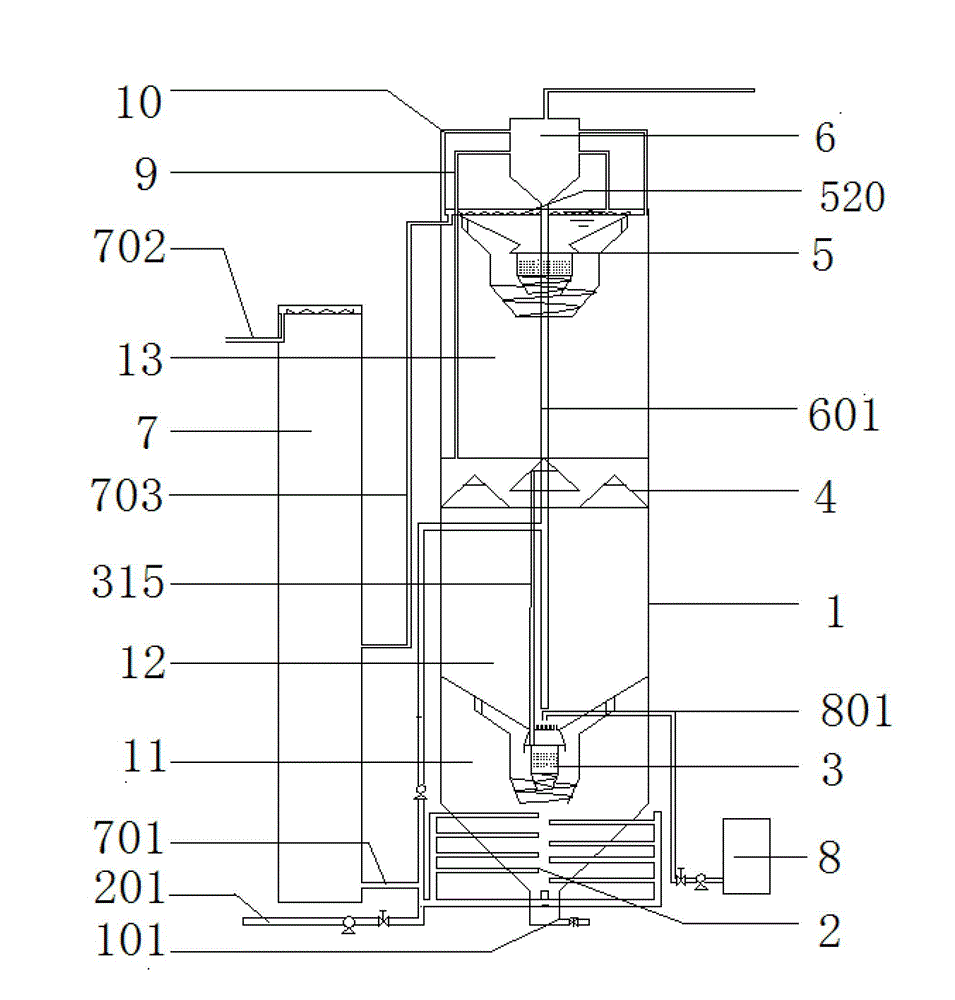
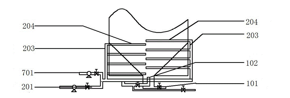
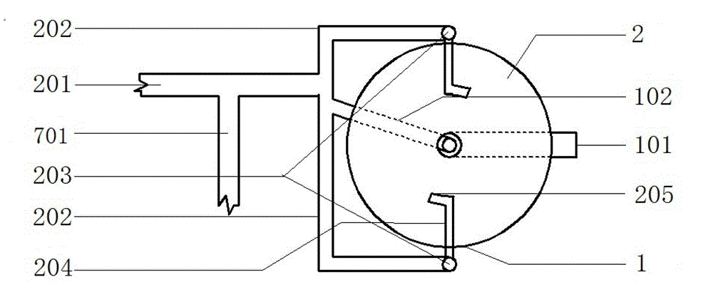
[0034] Such as figure 1 As shown, a two-phase two-stage anaerobic bioreactor for treating wastewater includes a reactor body 1, a circulating water tank 7 and an alkali adding device 8; the reactor body 1 is a hollow cylinder structure, and the reactor body 1 A water distributor 2 is provided at the bottom, a gas-liquid separator 6 is provided at the top of the reactor body 1, and a biological phase separator 3, a first-stage three-phase separator 4, a second-stage three-phase separator, and a second-stage three-phase separator are sequentially arranged in the reactor body 1 from bottom to top. A phase separator 5, the bottom of the reactor body 1 is provided with a sealed acidification reaction chamber 11, the height-to-diameter ratio of the acidification reaction chamber 11 is 1:1, and the biological phase separator 3 is located in the acidification reaction chamber 11; A methanogenic main reaction zone 12 is formed between the upper part of the acidification reaction chambe...
Embodiment 2
[0046] The difference between this embodiment and embodiment 1 is:
[0047] Such as Figure 2c As shown, the two water distribution pipes 202 are not in the same vertical plane, and the water outlets of the water distribution pipes 204 on the two water distribution pipes 202 are in opposite directions, and they are arranged on both sides of the central axis of the cylinder and on the horizontal plane. At the midpoint of the radius of the circumference, so that the water outlet directions of the two water distribution and drainage pipes 202 are in the same clockwise direction.
Embodiment 3
[0049] The difference between this embodiment and embodiment 1 is:
[0050] Such as Figure 4c As shown, the cross-sectional shape of the sludge collection tank 403 is trapezoidal, and only one baffle plate is provided at the return joint between the gas collecting hoods, and the angle of the baffle plate is horizontal. A sludge collection tank 403 is provided below each gas collecting hood 401 .
PUM
 Abstract
Description
Claims
Application Information
 - R&D
- Intellectual Property
- Life Sciences
- Materials
- Tech Scout
- Unparalleled Data Quality
- Higher Quality Content
- 60% Fewer Hallucinations
Browse by: Latest US Patents, China's latest patents, Technical Efficacy Thesaurus, Application Domain, Technology Topic, Popular Technical Reports.
© 2025 PatSnap. All rights reserved.Legal|Privacy policy|Modern Slavery Act Transparency Statement|Sitemap|About US| Contact US: help@patsnap.com


