
Sterilization bioreactor

A bioreactor, barrel technology, applied in bioreactor/fermenter combination, specific-purpose bioreactor/fermenter, biochemical instruments, etc., can solve problems such as unfavorable, easily damaged cells, and large damage to plant cells. , to achieve the effect of facilitating the reaction and use, extending the flow distance, and ensuring the sterilization effect

Inactive Publication Date: 2021-01-15
陆秋波
View PDF0 Cites 0 Cited by
  • Summary
  • Abstract
  • Description
  • Claims
  • Application Information

AI Technical Summary

Problems solved by technology

[0002] When cultivating biological cells, it is necessary to use a sterilized bioreactor to react the biological cells in a sterile environment. The mechanically stirred sterilized bioreactor has a large operating range, a high degree of mixing, and wide adaptability. Widely used in large-scale production, the existing sterilized bioreactor basically has the advantages of convenient operation, high working reliability, and strong adaptability, and can meet the requirements for the use of aseptic reactions in biological cells. However, for the existing As far as the sterilization bioreactor is concerned, on the one hand, the shear force generated in the stirred tank is large, which is easy to damage the cells and directly affects the growth and metabolism of the cells, especially for the generation of secondary products. The higher the stirring speed, The greater the shear force generated, the greater the damage to plant cells, which is not conducive to the use of cells sensitive to shear force. On the other hand, it is not conducive to ensuring sufficient oxygen in the reactor, which may easily cause insufficient oxygen supply due to biological factors. It affects the growth, reproduction and biological reactions of biological cells. On the other hand, when using sterilized bioreactors for various reactions of biological cells, due to the need for ventilation, bacteria from the outside can easily pass through the air inlet or outlet. The air port enters the sterilized bioreactor, which is not conducive to ensuring the aseptic reaction of biological cells

Method used


Image

  • Sterilization bioreactor
  • Sterilization bioreactor
  • Sterilization bioreactor

Examples


Embodiment 1

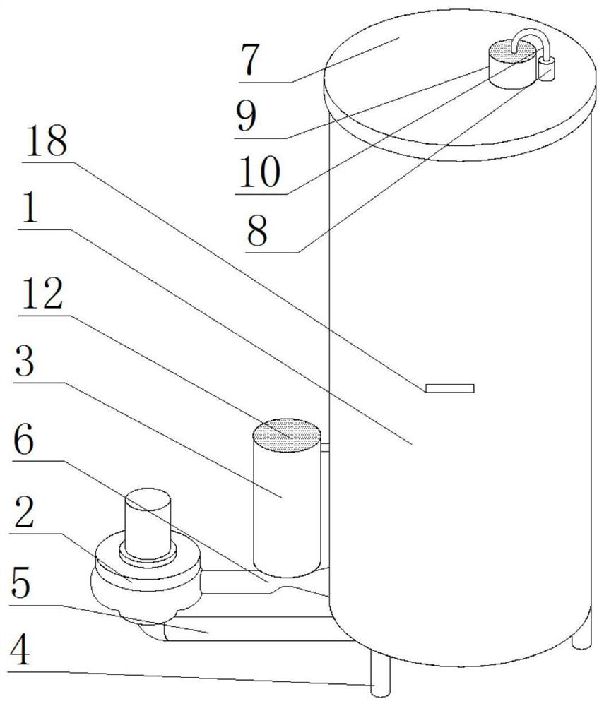
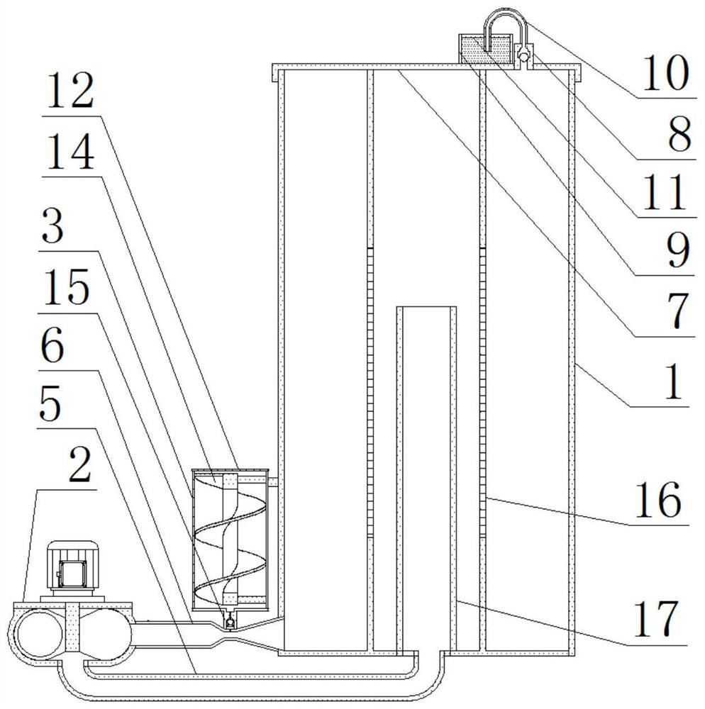
[0026] see figure 1 with figure 2 , the present invention provides a technical solution: a sterilizing bioreactor, including a barrel body 1, a water pump 2 and a sleeve 3, the sleeve 3 is welded on one side of the barrel body 1, and the water pump 2 is arranged on the barrel body One side of the body 1, the bottom of the bucket body 1 is welded with a bracket 4, the bottom of the water pump 2 is welded with a connecting pipe 5, one side of the water pump 2 is welded with a Venturi tube 6, and the bottom of the bucket body 1 is welded with a connecting pipe 5. A bung 7 is installed on the top, a one-way valve-8 is installed on the top of the bung 7, a ferrule 9 is welded on the top of the bung 7, and a trachea 10 is bonded on the top of the one-way valve-8, The top of the ferrule 9 is equipped with a filter screen 11 through bolts, the top of the sleeve 3 is equipped with a filter plate 12 through bolts, and the inner wall of the sleeve 3 is equipped with a disinfection lamp...

Embodiment 2

[0028] See figure 1 with Figure 4 The difference from Embodiment 1 is that the switch 18 is connected with the water pump 2 and the disinfection lamp 13 through wires, the bottom of the barrel body 1 is welded with a port, and one end of the connecting pipe 5 is welded at the bottom of the port , the water pump 2 communicates with the bottom of the barrel body 1 through the connecting pipe 5, one side of the water pump 2 communicates with the side of the barrel body 1 through the venturi tube 6, and one end of the venturi tube 6 is attached to On the inner wall of the barrel body 1, the water pump 2 can be turned on through the switch 18, and the water pump 2 can extract the liquid in the sleeve 1 through the connecting pipe 5, and spray it to the inner wall of the barrel body 1 through the Venturi tube 6, and the ejected liquid is along the The inner wall of the barrel body 1 flows, and then pushes the liquid in the barrel body 1 to rotate and flow in the barrel body 1, whi...

Embodiment 3

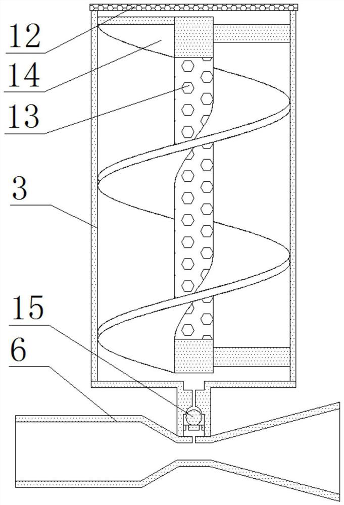
[0030] See image 3 The difference from Example 2 is that the top of the Venturi tube 6 is provided with an air hole, the check valve 2 15 is welded on the top of the air hole, the sleeve 3 communicates with the Venturi tube 6, and the liquid When the venturi tube 6 flows into the barrel body 1 at high speed, a negative pressure is generated in the middle of the venturi tube 6, and then a suction force is generated on the check valve 2 15 through the air hole, so that the air in the sleeve 3 enters the venturi tube 6, after the air enters the Venturi tube 6, it is dispersed by the high-speed flow of liquid, and then dispersed microbubbles are formed in the liquid. Using the characteristics that the microbubbles can stay in the liquid for a long time, the liquid is greatly improved. The amount of dissolved oxygen, thereby ensuring sufficient oxygen supply in the barrel body 1, and ensuring the oxygen consumption of the biological reaction.


PUM


Abstract

The invention provides a sterilization bioreactor. The sterilization bioreactor comprises a barrel body, a water pump and a sleeve; a support is welded to the bottom of the barrel body; a connecting tube is welded to the bottom of the water pump; a venturi tube is welded to one side of the water pump; a barrel cover is installed at the top of the barrel body; a clamping sleeve is welded to the topof the barrel cover; a filter screen is arranged at the top of the clamping sleeve through a bolt; a filter plate is arranged at the top of a sleeve through a bolt; and a disinfection lamp is arranged on the inner wall of the sleeve through a bolt. By virtue of the sterilization bioreactor, the inside of the barrel body can be well mixed and stirred, damage to biological cells caused by shearingforce generated by mechanical stirring can be avoided, the safety of the biological cells is guaranteed, and the dissolved oxygen content of liquid is increased, so that sufficient oxygen supply in the barrel body is guaranteed, oxygen consumption of biological reaction is guaranteed, bacteria in air are prevented from reversely entering the barrel body in a wall growth mode, the sterile environment in the barrel body is guaranteed, and the sterilization bioreactor is suitable for culture of sterilized cells.

Description

technical field [0001] The invention relates to the technical field of sterilization bioreactors, in particular to a sterilization bioreactor. Background technique [0002] When cultivating biological cells, it is necessary to use a sterilized bioreactor to react the biological cells in a sterile environment. The mechanically stirred sterilized bioreactor has a large operating range, a high degree of mixing, and wide adaptability. Widely used in large-scale production, the existing sterilized bioreactor basically has the advantages of convenient operation, high working reliability, and strong adaptability, and can meet the requirements for the use of aseptic reactions in biological cells. However, for the existing As far as the sterilization bioreactor is concerned, on the one hand, the shear force generated in the stirred tank is large, which is easy to damage the cells and directly affects the growth and metabolism of the cells, especially for the generation of secondary p...

Claims


Application Information

Patent Timeline
Patent Type & Authority Applications(China)
IPC IPC(8): C12M1/00C12M1/12C12M1/04A61L9/18A61L9/00
CPCA61L9/00A61L9/18C12M23/02C12M23/38C12M23/48C12M29/04C12M29/06
Inventor 陆秋波李雄富庞洁
Owner 陆秋波
Learn More