
A robot-based inspection line for rotor blades

A robotic technology and rotor blade technology, applied in the field of rotor blade detection lines, can solve the problems of time-consuming and laborious positioning or unlocking process, affecting detection accuracy, rotor blade damage, etc., to avoid detection accuracy, avoid damage, and tightly adsorb and fix Effect

Active Publication Date: 2021-12-10
张辉
View PDF6 Cites 0 Cited by
  • Summary
  • Abstract
  • Description
  • Claims
  • Application Information

AI Technical Summary

Problems solved by technology

[0003] The existing rotor blade inspection line uses hoisting equipment to place the rotor blades on the positioning fixture, and then conducts quality inspection on the surface of the rotor blades. However, the hoisting equipment and the rotor blades are usually connected and fixed by wire ropes, which is easy to cause damage to the rotor blades. It affects the detection accuracy, and it is difficult for the detection equipment to judge whether the surface damage is the damage during the processing or the damage during the hoisting process; at the same time, the conventional fixture has a complex structure, and the positioning or unlocking process is time-consuming and laborious, which is difficult to meet the needs of rapid detection

Method used


Image

  • A robot-based inspection line for rotor blades
  • A robot-based inspection line for rotor blades
  • A robot-based inspection line for rotor blades

Examples


Embodiment Construction

[0022] In order to make the above objects, features and advantages of the present invention more comprehensible, specific implementations of the present invention will be described in detail below in conjunction with the accompanying drawings.

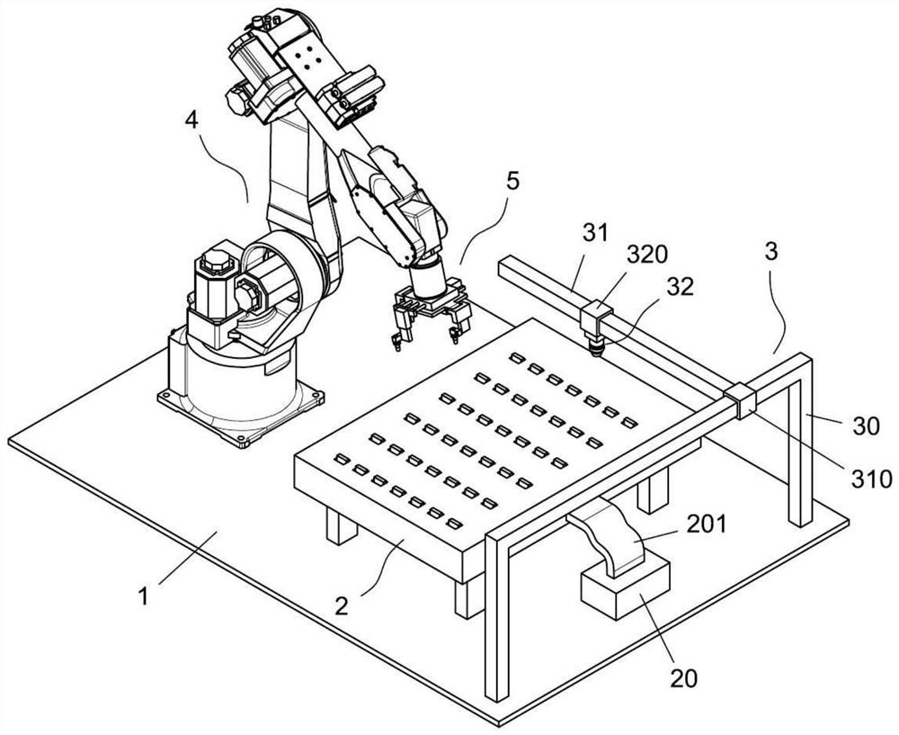
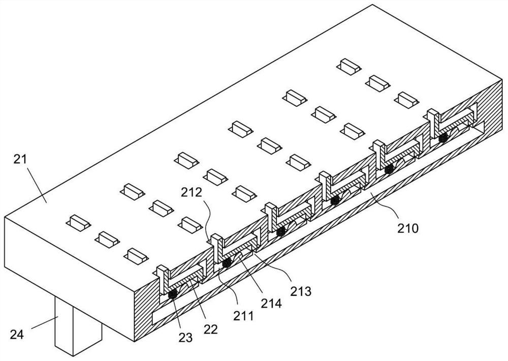
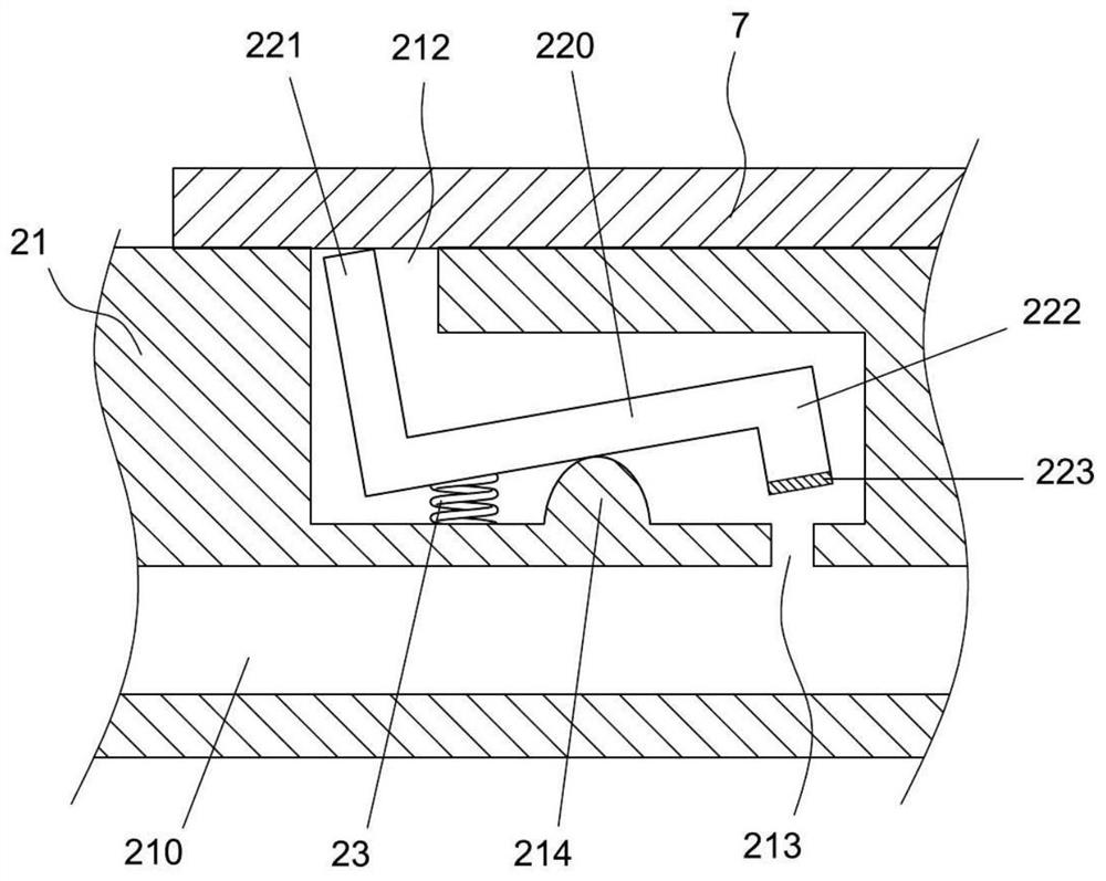
[0023] like Figure 1-8 As shown, a robot-based rotor blade detection line includes a multi-degree-of-freedom hoisting robot 4 fixed on the base 1, a positioning mechanism 2 for fixing the rotor blade 7, and a detection unit 3 for detecting the rotor blade 7 And a control system (not shown in the figure), wherein, the positioning mechanism 2 is located between the multi-degree-of-freedom lifting robot 4 and the detection unit 3, and the control system is connected with the multi-degree-of-freedom lifting robot 4, the positioning mechanism 2 and the detection unit 3. Electrical connection; the end of the multi-degree-of-freedom hoisting robot 4 is connected with a material transfer manipulator 5 .

[0024] The positioning mechanism 2 i...


PUM


Abstract

The invention discloses a rotor blade detection line based on robot technology. During the rotor blade detection process, a multi-degree-of-freedom hoisting robot hoistes the produced rotor blades to a positioning mechanism, and the positioning mechanism can position the rotor blades so that for detection operations. Considering that the structural feature of the rotor blade is an irregular curved surface structure, the material transfer manipulator of this application is not a conventional manipulator structure, and it realizes the position change and adjustment of multiple material transfer suction heads through a unique structure, thereby Make the material transfer suction head fully contact with the rotor blades, and then achieve tight adsorption and fixation to ensure the safety of hoisting. At the same time, due to the negative pressure adsorption, it can avoid damage to the surface of the rotor blades and avoid affecting the detection accuracy while hoisting safely. .

Description

technical field [0001] The invention relates to the technical field of robot devices, in particular to a robot-based rotor blade detection line. Background technique [0002] With the gradual intensification of the global energy crisis, wind energy, solar energy and other environmentally friendly energy sources have attracted more and more attention. For wind turbines, the rotor blades are an indispensable component. The rotor blades capture and transmit the wind force to the shaft, thereby realizing the conversion of wind energy into electrical energy. The quality of the rotor blades is related to the stability of the operation of the wind turbine. [0003] The existing rotor blade inspection line uses hoisting equipment to place the rotor blades on the positioning fixture, and then conducts quality inspection on the surface of the rotor blades. However, the hoisting equipment and the rotor blades are usually connected and fixed by wire ropes, which is easy to cause damage...

Claims


Application Information

Patent Timeline
Patent Type & Authority Patents(China)
IPC IPC(8): G01N21/88B25J9/00B25J15/06
CPCG01N21/8851B25J9/00B25J15/0616
Inventor 不公告发明人
Owner 张辉
Learn More