Automatic smoke removal system of laparoscope

An automatic clearing and laparoscopic technology, applied in medical science, surgical instruments for suctioning substances, surgery, etc., can solve problems such as difficulty in obtaining dense point cloud information, image distortion, and increased difficulty of surgery, so as to eliminate subjective factors and the outside world Effects of factors, correction of distortion and deviation, and effect of reducing the difficulty of surgery

Inactive Publication Date: 2019-04-16
聊城市光明医院
View PDF4 Cites 6 Cited by
  • Summary
  • Abstract
  • Description
  • Claims
  • Application Information

AI Technical Summary

Problems solved by technology

[0004] The laparoscopic smoke automatic removal system in the prior art has poor smoke removal effect
[0005] The 3D point cloud reconstructed by existing laparoscopes is extremely sparse, and the topological structure information of the object cannot be reconstructed, especially in the case of specular reflection (highlight), due to the existence of light sources on the laparoscope and the smoothness of the organ surface, usually A highlighted area is formed on the surface of the organ, which makes it difficult for the existing 3D point cloud reconstruction scheme to obtain dense point cloud information; at the same time, the surgeon manually adjusts the endoscope by visually measuring the distance from the end of the endoscope lens to the front end of the poking card. The lens can be placed in the front of the poking card. This adjustment method is not only slow, inaccurate, and subjective, but also easily affected by external factors, which increases the difficulty of the operation and reduces the efficiency of the operation; the image acquired by the abdominal camera is distorted. The problem is serious and the deviation is large; the image details are not displayed well

Method used


Image

  • Automatic smoke removal system of laparoscope
  • Automatic smoke removal system of laparoscope
  • Automatic smoke removal system of laparoscope

Examples


Embodiment Construction

[0070] In order to further understand the content, features and effects of the present invention, the following examples are given, and detailed descriptions are given below with reference to the accompanying drawings.

[0071] The structure of the present invention will be described in detail below in conjunction with the accompanying drawings.

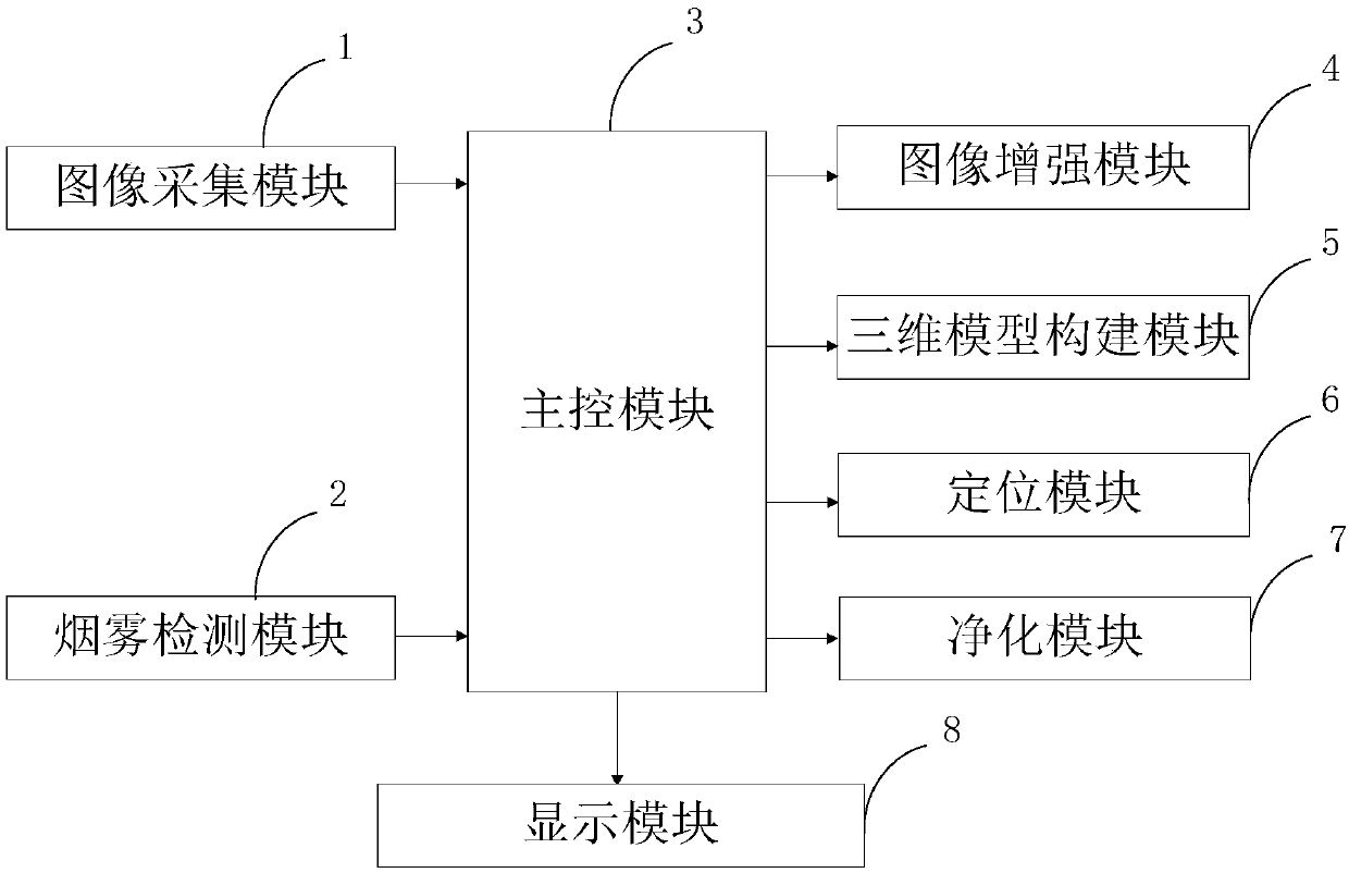
[0072] Such as figure 1 As shown, the laparoscopic smoke automatic removal system provided by the present invention includes: an image acquisition module 1, a smoke detection module 2, a main control module 3, an image enhancement module 4, a three-dimensional model building module 5, a positioning module 6, a purification module 7, a display Module 8.

[0073] The image acquisition module 1 is connected with the main control module 3, and is used to collect abdominal cavity image data in real time through the laparoscopic camera;

[0074] The smoke detection module 2 is connected with the main control module 3, and is used for rea...


PUM


Abstract

The invention belongs to the technical field of automatic smoke removal of laparoscopes and discloses an automatic smoke removal system of a laparoscope. The automatic smoke removal control system ofthe laparoscope comprises an image acquisition module, a smoke detection module, a main control module, an image enhancement module, a three-dimensional model construction module, a locating module, apurification module and a display module. According to the system, the optical locating system in existing surgical operation navigation is fully utilized through the three-dimensional model construction module, other hardware equipment does not need to be introduced, the working flow of existing laparoscopic navigation cannot be influenced, and therefore the system is more economical and direct;meanwhile, a moving path of the tail end of an endoscope head is determined through the locating module according to the known distance and the known angle, and therefore the tail end of the endoscope head can be quickly and accurately moved to a to-be-measured point of a stamp card along the moving path. Moreover, the influences of subjective factors and external factors are eliminated, so thatthe operation difficulty is greatly reduced, and the operation efficiency is improved.

Description

technical field [0001] The invention belongs to the technical field of laparoscopic smoke automatic removal, in particular to a laparoscopic smoke automatic removal system. Background technique [0002] A laparoscope is an instrument with a tiny camera. Laparoscopic surgery is performed using laparoscopes and related instruments: using a cold light source to provide illumination, inserting a laparoscopic lens (3-10 mm in diameter) into the abdominal cavity, and using digital camera technology to make the images captured by the laparoscopic lens pass through the light guide The fiber is conducted to the post-stage signal processing system and displayed on a dedicated monitor in real time. Then the doctor analyzes and judges the patient's condition through the images of different angles of the patient's organs displayed on the monitor screen, and uses special laparoscopic instruments to perform the operation. Laparoscopic surgery mostly uses 2-4 hole operations, one of which...

Claims


Application Information

Patent Timeline
Patent Type & Authority Applications(China)
IPC IPC(8): A61B18/00
CPCA61B18/00A61B2218/001A61B2218/008
Inventor 许长起
Owner 聊城市光明医院
Why Eureka
Try Eureka