Gear machining device

A technology for processing devices and gears, which is applied in grinding drive devices, metal processing equipment, grinding/polishing safety devices, etc., can solve the problems of complex structure, affecting the quality and efficiency of gear processing, and difficult to collect metal scraps. The effect of improving efficiency and quality, improving usability

Inactive Publication Date: 2019-04-16
ANHUI JISITE INTELLIGENT EQUIP CO LTD
View PDF6 Cites 8 Cited by
  • Summary
  • Abstract
  • Description
  • Claims
  • Application Information

AI Technical Summary

Problems solved by technology

However, the existing gear processing device has a complex structure, and the metal debris generated during the work of the internal grinding result is not easy to collect, which easily affects the quality and efficiency of gear processing

Method used


Image

  • Gear machining device
  • Gear machining device
  • Gear machining device

Examples


Embodiment 1

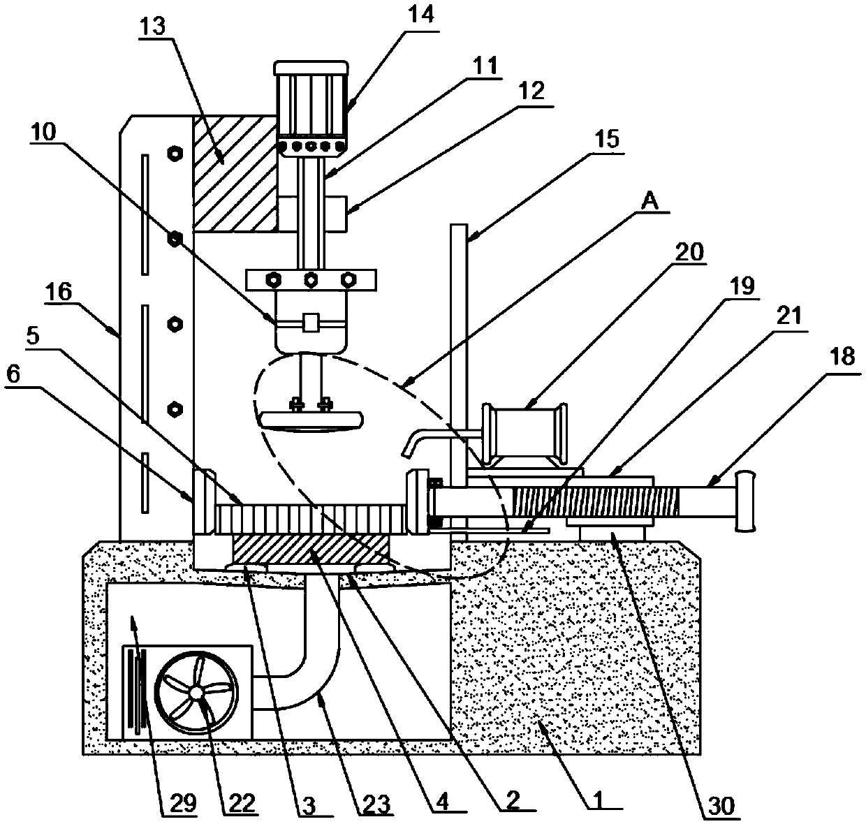
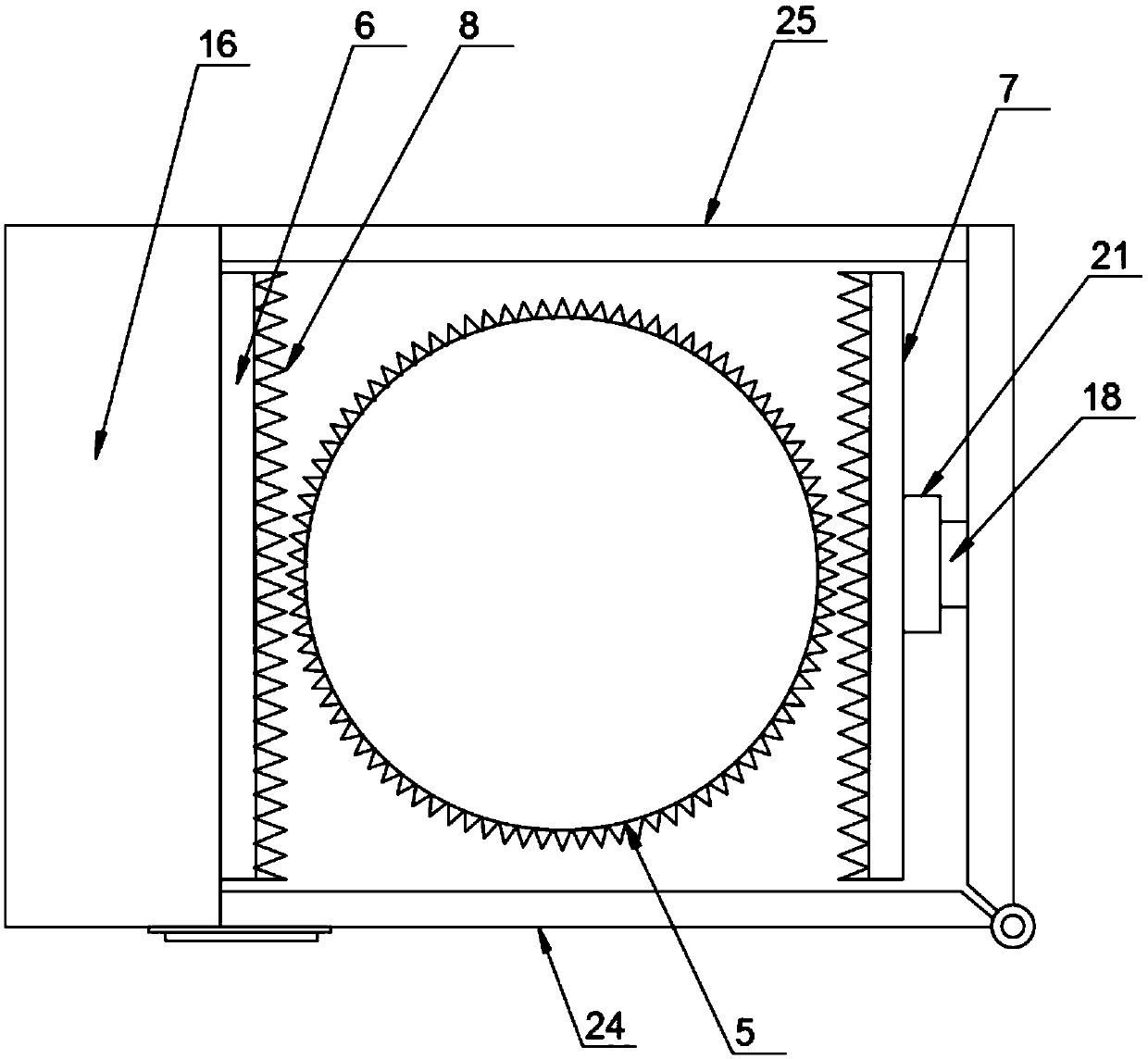
[0023] Such as Figure 1-4 The shown gear processing device includes a machine body 1, a processing tank 2 is embedded on the top of the machine body 1, a pad 3 is provided at the bottom of the inner cavity of the processing tank 2, and a backing plate 4 is provided on the top of the pad 3 , the top of the backing plate 4 is provided with a gear 5, one side of the gear 5 is provided with a fixed clamping plate 6 and the other side is provided with a movable clamping plate 7, the inner side of the fixed clamping plate 6 and the movable clamping plate 7 insides are provided with matching teeth 8, and the top of the gear 5 is provided with a grinding disc 9, and the top of the grinding disc 9 is provided with a high-torque motor 10, and the top of the high-torque motor 10 is provided with a telescopic rod 11, and the telescopic rod 11 The outer wall is covered with a sleeve 12, one side of the sleeve 12 is provided with a fixed platform 13, the top of the telescopic rod 11 is pro...

Embodiment 2

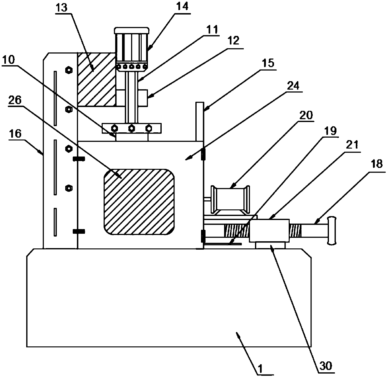
[0027] Such as Figure 1-4 A kind of gear 1 processing device shown, the front side wall of the partition plate 15 is provided with a fan door 24 and the rear side wall is provided with a baffle plate 25, and the described fan door 24 is embedded with a glass window 26, and the glass window 26 is made of double-layer tempered glass material. One side of the door 24 is provided with a hinge shaft and the other side is provided with a latch lock. One side of the door 24 is movably connected with the partition 15 through a hinge shaft and the other It is detachably connected to the support rod 16 through a latch lock;

[0028] Further, in the above technical solution, the number of the pads 3 is multiple, the pads 3 are fixed on the bottom wall of the processing tank 2, and the support rods 16 and the partitions 15 are fixed on the machine body 1, the side wall of the fixed clamping plate 6 is fixedly connected to the side wall of the support rod 16, and the bottom height of the...


PUM


Abstract

The invention discloses a gear machining device. The gear machining device comprises a machine body, a machining groove is embedded into the top of the machine body, a cushion block is arranged at thebottom of an inner cavity of the machining groove, a base plate is arranged at the top of the cushion block, a gear is arranged at the top of the base plate, and a fixed clamping plate is arranged onone side of the gear and a movable clamping plate is arranged on the other side of the gear. Anastomotic teeth are arranged on the inner sides of the fixed clamping plate and the movable clamping plate, a grinding disc is arranged at the top of the gear, a high torque motor is arranged at the top of the grinding disc, telescopic rods are arranged at the top of the high torque motor, and a sleevesleeves the outer walls of the telescopic rods. According to the gear machining device, by arranging a relatively sealed environment, wind power generated by a pipeline draught fan is used for actingon the gear end surface for being ground through an air blowing pipe, metal debris after grinding is blown, suction generated by a dust collector collects the debris upfloated in the machining groovethrough a dust collecting pipe, and the efficiency and quality of removing burrs of the gear are improved.

Description

technical field [0001] The invention relates to the mechanical field, in particular to a gear processing device. Background technique [0002] A gear is a mechanical element that transmits motion and power through continuous meshing of gear teeth. Due to the smooth transmission of gears, it is widely used in mechanical transmission and the entire mechanical field. Gears can be divided into four categories, including spur gears, bevel gears, ring gears, and special purpose gears. However, the structure of the existing gear processing device is complicated, and the metal scraps generated during the work of the internal grinding result are not easy to be collected, which easily affects the quality and efficiency of gear processing. [0003] Therefore, it is necessary to invent a gear processing device to solve the above problems. Contents of the invention [0004] The purpose of the present invention is to provide a gear processing device. By setting a relatively closed env...

Claims


Application Information

Patent Timeline
Patent Type & Authority Applications(China)
IPC IPC(8): B24B9/04B24B7/16B24B7/07B24B41/06B24B47/12B24B55/04B24B55/06B24B55/12
CPCB24B7/07B24B7/16B24B9/04B24B41/06B24B47/12B24B55/04B24B55/06B24B55/12
Inventor 王兴松许飞云罗翔戴挺章功国
Owner ANHUI JISITE INTELLIGENT EQUIP CO LTD
Why Eureka
Try Eureka