
Quick loading and unloading device for mechanical field

A loading and unloading device, technology in the field, applied in the directions of grinding/polishing safety device, dryer, drying gas arrangement, etc., can solve the problems of reduced production efficiency, trouble for users, inability to meet workpiece plate clamping and fixing, etc. The effect of sturdiness

Inactive Publication Date: 2019-04-16
江苏博伟自动化设备有限公司
View PDF1 Cites 2 Cited by
  • Summary
  • Abstract
  • Description
  • Claims
  • Application Information

AI Technical Summary

Problems solved by technology

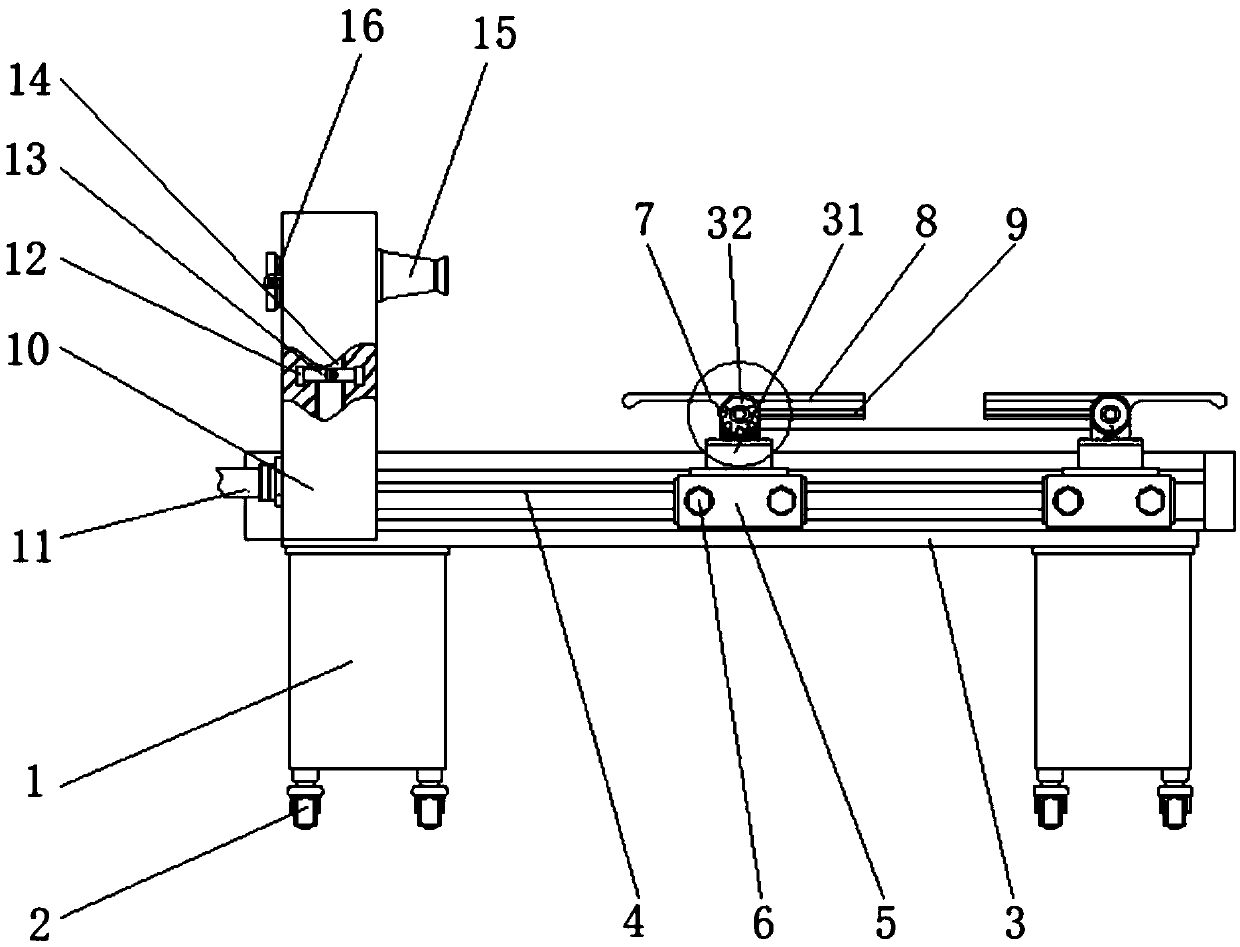
[0004] The purpose of the present invention is to provide a quick loading and unloading device for the mechanical field to solve the problem that the existing loading and unloading device proposed in the above background technology cannot clamp and fix the workpiece plate in use, and at the same time cannot perform quick disassembly and assembly, resulting in It reduces production efficiency during use, is not convenient for users to use, and does not have simple cleaning and drying functions, which brings troublesome problems to users.

Method used


Image

  • Quick loading and unloading device for mechanical field
  • Quick loading and unloading device for mechanical field
  • Quick loading and unloading device for mechanical field

Examples


Embodiment Construction

[0026] The following will clearly and completely describe the technical solutions in the embodiments of the present invention with reference to the accompanying drawings in the embodiments of the present invention. Obviously, the described embodiments are only some, not all, embodiments of the present invention. Based on the embodiments of the present invention, all other embodiments obtained by persons of ordinary skill in the art without making creative efforts belong to the protection scope of the present invention.

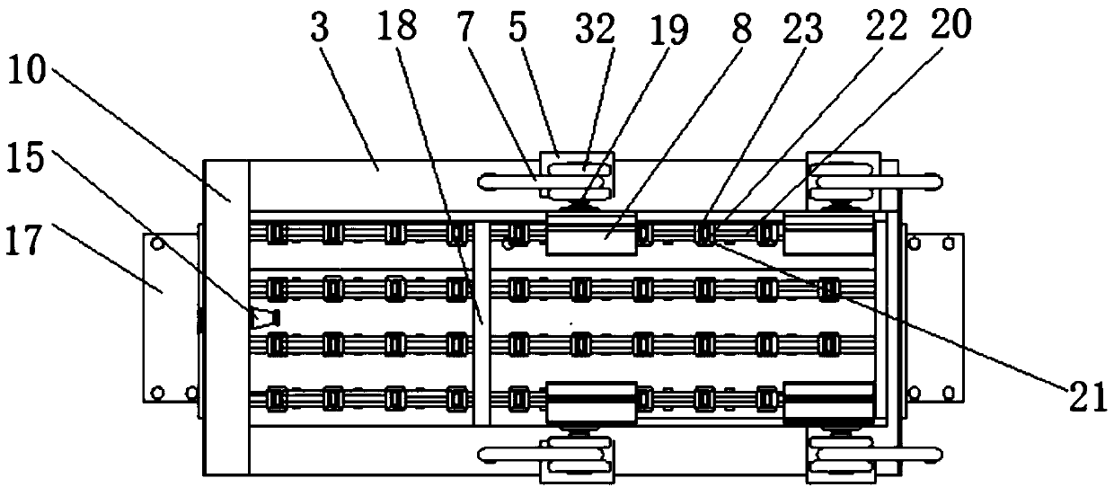
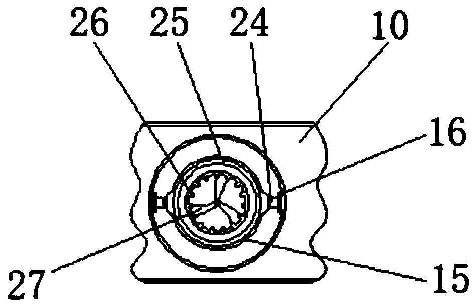
[0027] see Figure 1-5, the present invention provides a technical solution: a quick loading and unloading device for the mechanical field, including a base 1, a wheel 2, a lathe 3, a first slide rail 4, a first slider 5, a hexagonal screw 6, a handle 7, a splint 8, Upholstery layer 9, bracket 10, water pipe 11, fixing block 12, clamp hoop 13, hose 14, sprinkler head 15, connection ring 16, side plate 17, baffle plate 18, V-shaped connector 19, second slide ra...


PUM


Abstract

The invention relates to a quick loading and unloading device for the mechanical field. The quick loading and unloading device comprises a base, a first sliding rail and a supporting table. Wheels areconnected to two sides of the lower end of the base. A turning lathe is arranged at the upper end of the base. The first sliding rail is embedded in the middle of the outer wall of the turning lathe.A first sliding block is mounted on the outer wall of the first sliding rail. Hex head screws are arranged on two sides of the first sliding block. The supporting table is fixed to the top of the first sliding block. Rotating shafts are arranged at the top of the supporting table. A handle is connected to the left end in each rotating shaft. V-shaped connecting components penetrate through the middles of the rotating shafts. Clamping plates are mounted at the tail ends of the V-shaped connecting components. Soft padding layers are embedded in the bottoms of the clamping plates. The base and the turning lathe are arranged and are welded into an integral structure. The base and the turning lathe are stable, so that the turning lathe can horizontally run during operation, a workpiece plate is prevented from sliding along two sides of the turning lathe during application and causing inconvenient clamping and fixing subsequently.

Description

technical field [0001] The invention relates to the technical field of mechanical processing, in particular to a quick loading and unloading device for the mechanical field. Background technique [0002] Machining refers to the process of changing the shape, size or performance of the workpiece plate through a mechanical device. According to the difference in processing methods, it can be divided into cutting processing and pressure processing. The whole process of finished products includes the transportation and storage of raw materials, production preparation, blank manufacturing, parts processing and heat treatment, product assembly, debugging, painting and packaging, etc. for machine production. The content of the production process is very Widely, the workpiece plate needs to be welded during the production process. During the welding process, some impurities may appear on the surface of the workpiece plate, resulting in insufficient fixation of the solder joints and i...

Claims


Application Information

Patent Timeline
Patent Type & Authority Applications(China)
IPC IPC(8): B24B41/00B24B41/06B24B55/00B08B3/02F26B21/00
CPCB08B3/02B24B41/00B24B41/06B24B55/00F26B21/00F26B21/001
Inventor 杨旭
Owner 江苏博伟自动化设备有限公司
Learn More