Supercharge Your Innovation With Domain-Expert AI Agents!

Efficient injection molding mechanical hand

A manipulator and high-efficiency technology, applied in the field of high-efficiency injection molding manipulators, can solve the problems of insufficient protection, low use efficiency, and insufficient manipulator flexibility, and achieve the effects of good self-protection, high use efficiency, and improved efficiency

Inactive Publication Date: 2019-04-16
青岛崇源电子有限公司
View PDF13 Cites 2 Cited by
  • Summary
  • Abstract
  • Description
  • Claims
  • Application Information

AI Technical Summary

Problems solved by technology

But the flexibility of the manipulator is insufficient, its own protection is not enough, and the use efficiency is low

Method used


Image

  • Efficient injection molding mechanical hand
  • Efficient injection molding mechanical hand
  • Efficient injection molding mechanical hand

Examples


Embodiment 1

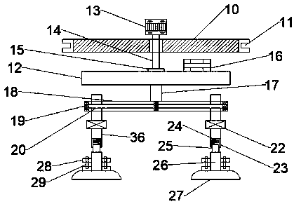
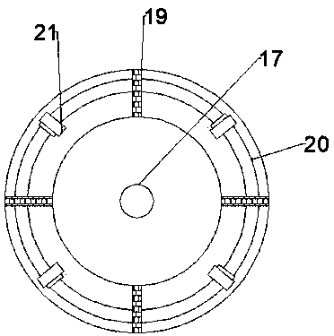
[0019] see Figure 1-3 , a high-efficiency injection molding manipulator, including a mounting plate 10, the left and right sides of the mounting plate 10 are provided with mounting openings 11, through which the entire manipulator can be installed at the position to be used. A rotating motor 13 is provided at the top middle position of the mounting plate 10, and the lower output end of the rotating motor 13 is rotatably connected with a vertical rotating rod 14, and the bottom end of the rotating rod 14 is fixedly equipped with a turntable 15, and the bottom end of the turntable 15 is A placement board 12 is fixedly installed, and a tool cabinet 16 is fixedly placed on one side of the top of the placement board 12. The setting of the tool cabinet 16 can provide some convenience for the staff. A connecting rod 17 is fixedly connected to the center of the bottom of the placement plate 12 , and a circular mounting frame 18 is fixedly connected to the bottom end of the connecting...

Embodiment 2

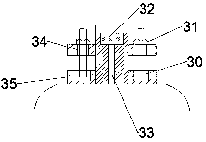
[0022] On the basis of Embodiment 1, an air conditioner 32 is provided on the inner top of the mounting seat 26, and the lower side of the air conditioner 32 is communicated with a cold air pipe 33, and the end of the cold air pipe 33 extends into the inner top of the suction cup 27. The cold air produced by the air conditioner 32 is transported to the inside of the suction cup 27 by the cold air pipe 33 to cool down the forming mold to be adsorbed, so as to prevent the service life of the suction cup 27 from being damaged due to the high temperature of the product to be adsorbed.


PUM


Abstract

The invention relates to the technical field of injection molding machine production equipment, and discloses an efficient injection molding mechanical hand. The efficient injection molding mechanicalhand comprises a mounting plate. A rotary motor is arranged at the middle position of the top of the mounting plate, the output end of the lower side of the rotary motor is rotationally connected with a vertical rotary rod, the center position of the bottom of a containing plate is fixedly connected with a connecting rod, the bottom end of the connecting rod is fixedly connected with a round mounting frame, four sets of sliding rods are arranged on the mounting frame, vertical sliding blocks are slidingly connected to the sliding rods, a baffle is fixedly mounted between every two sliding rods, the bottoms of the sliding blocks are fixedly connected with air cylinders, piston rods are arranged on the lower sides of the air cylinders, U-shaped blocks are fixedly mounted at the bottom endsof the piston rods, springs are arranged in the U-shaped blocks, the tops of the springs are elastically connected to the inner tops of the U-shaped blocks, the bottom ends of the springs are elastically connected with sleeve columns, the bottom ends of the sleeve columns are fixedly connected with mounting bases, and suckers are arranged at the bottoms of the mounting bases. The efficient injection molding mechanical hand has the beneficial effects of being good in flexibility, good in self-protection performance and high in use efficiency.

Description

technical field [0001] The invention relates to the technical field of injection molding machine production equipment, in particular to an efficient injection molding manipulator. Background technique [0002] Injection molding machine is also known as injection molding machine or injection machine. It is the main molding equipment for making thermoplastics or thermosetting plastics into various shapes of plastic products using plastic molding molds. Divided into vertical, horizontal, all-electric. The injection molding machine heats the plastic, applies high pressure to the molten plastic, and makes it shoot out to fill the mold cavity. Injection molding machines are the main production equipment for plastic and rubber products. In view of the advantages of hydraulic pressure, such as low cost, small volume, long life, high degree of automation, and good reliability, most injection molding machines use hydraulic systems. Existing injection molding machines are generally ...

Claims


Application Information

Patent Timeline
IPC IPC(8): B29C45/42B29C45/73
CPCB29C45/42B29C45/4225B29C45/7337B29C2045/4266
Inventor 张建
Owner 青岛崇源电子有限公司
Features
  • R&D
  • Intellectual Property
  • Life Sciences
  • Materials
  • Tech Scout
  • Unparalleled Data Quality
  • Higher Quality Content
  • 60% Fewer Hallucinations
Learn More