
Aluminium alloy template used for variable cross-section of wall column and design method of aluminium alloy template

A technology of aluminum alloy formwork and variable cross-section, which is applied in the fields of formwork/formwork/work frame, connectors of formwork/formwork/work frame, and on-site preparation of building components, which can solve the problem of high processing cost and duplication of spare formwork Problems such as low utilization rate achieve the effect of reducing construction cost and simple operation

Inactive Publication Date: 2019-04-16
广西微比建筑科技有限公司 +1
View PDF0 Cites 2 Cited by
  • Summary
  • Abstract
  • Description
  • Claims
  • Application Information

AI Technical Summary

Problems solved by technology

The disadvantage of the existing wall column transformation layer formwork method technology is that a large number of spare formworks need to be designed for each transformation layer wall column, and the spare formwork is only designed for a certain variable section wall column of a certain building. The size is different, so the reuse rate of spare templates for such transformation layers is low, resulting in high material and processing costs

Method used


Image

  • Aluminium alloy template used for variable cross-section of wall column and design method of aluminium alloy template
  • Aluminium alloy template used for variable cross-section of wall column and design method of aluminium alloy template
  • Aluminium alloy template used for variable cross-section of wall column and design method of aluminium alloy template

Examples


Embodiment 1

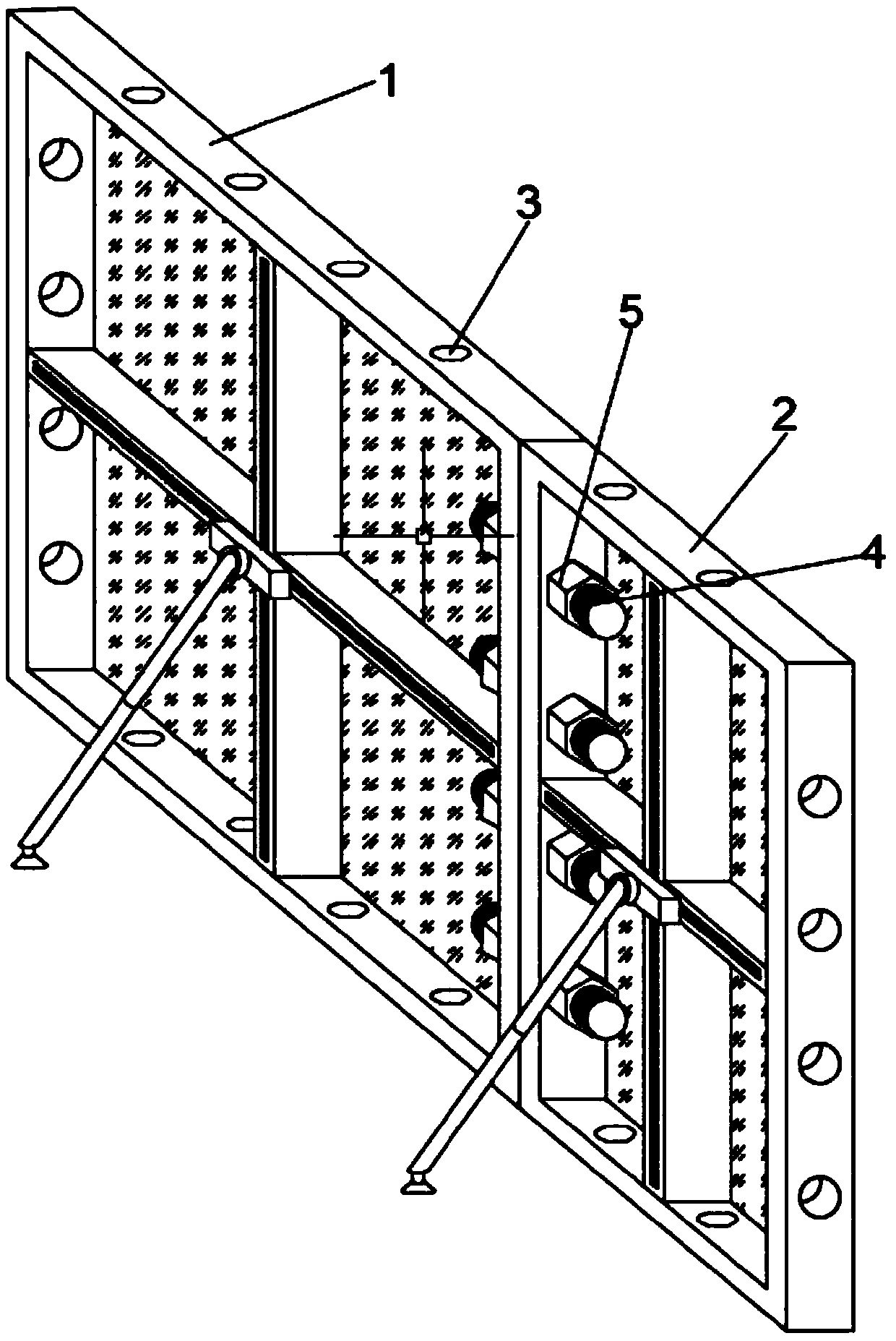
[0033] Embodiment 1: refer to figure 1 and 2 ;

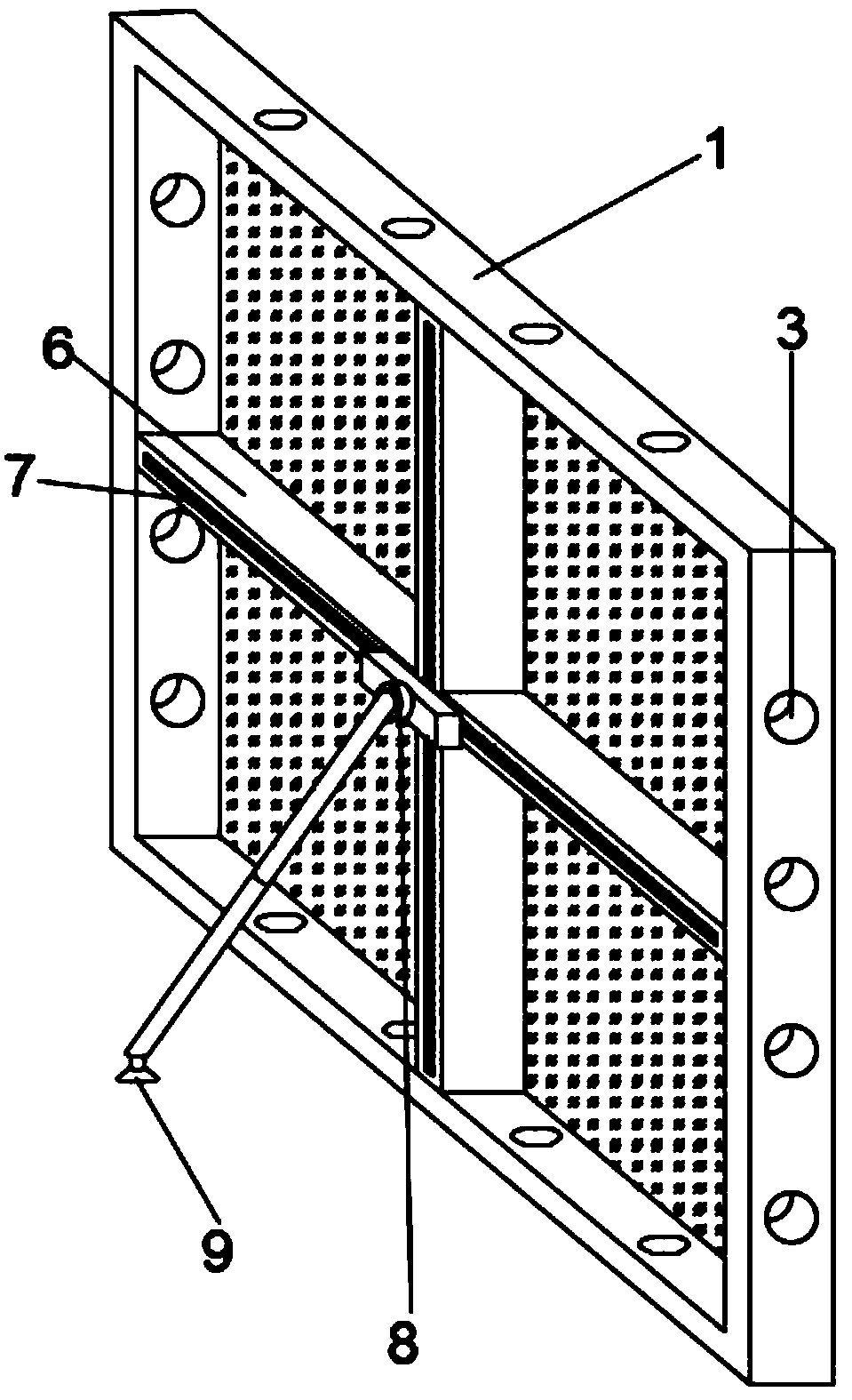
[0034] An aluminum alloy formwork for a variable section of a wall column, comprising a wide-side aluminum alloy formwork 1 and a narrow-side aluminum alloy formwork 2, the wide-side aluminum alloy formwork 1 and the narrow-side aluminum alloy formwork 2 are provided with formwork connecting pin holes 3, and the formwork The connecting pin hole 3 is penetrated by bolts 4, and the bolts 4 are threaded to connect the nuts 5. The wide-side aluminum alloy formwork 1 and the narrow-side aluminum alloy formwork 2 are spliced ​​by bolts 4; the wide-side aluminum alloy formwork 1 and the narrow-side aluminum alloy formwork 2 also include There is a cross reinforcement frame 6, a diagonal bracing device 8 and a friction support device 9, and the back of the wide-side aluminum alloy formwork 1 and the narrow-side aluminum alloy formwork 2 is fixedly connected with a cross reinforcement frame 6, and the outer surface of the cross reinforc...

Embodiment 2

[0036] Embodiment 2: The difference based on Embodiment 1 is;

[0037] The cross reinforcement frame 6 also includes a ball groove 15, a sliding opening 16 and a draw-in groove 17, the front end of the middle part of the cross reinforcement frame 6 is provided with a ball groove 15, the inner end of the cross reinforcement frame 6 is provided with a sliding opening 16, the bottom surface of the cross reinforcement frame 6, etc. Multiple sets of card slots 17 are arranged.

[0038] The diagonal support device 8 includes a connecting rod 10, a support seat 11, a rotating head 12, a splicable support rod 13 and a rolling ball 18. The rolling ball 18 is slidably connected with the ball groove 15. The middle part of the rolling ball 18 is provided with a through opening 19, which can be spliced. The lower end of the support rod 13 is movably connected with a friction support device 9, the upper end of the splicable support rod 13 is rotationally connected with the outer end of the ...

Embodiment 3

[0042] Embodiment 3: the difference based on the basis of embodiment 1 or embodiment 2 is;

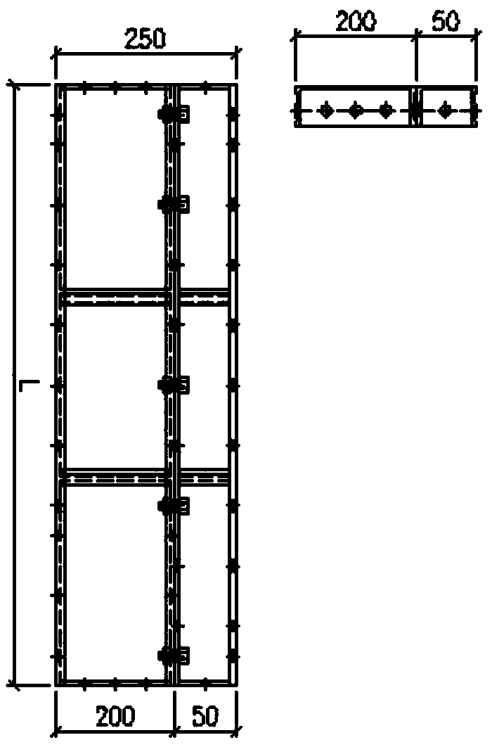
[0043] A design method for an aluminum alloy formwork when a wall column has a variable section, the method uses the aluminum alloy formwork for a wall column with a variable section according to claims 1-4, and the method includes:

[0044] S1, making wide-side aluminum alloy formwork 1 and narrow-side aluminum alloy formwork 2 with different width specifications and standards, and transporting wide-side aluminum alloy formwork 1 and narrow-side aluminum alloy formwork 2 to the construction site for wall column section transformation;

[0045] S2. Comparing the construction drawings of the wall column structure, determine the width dimension X+Y before the wall column section transformation layer transformation and the width dimension X after the wall column section transformation layer transformation, and then calculate the wall column section transformation layer transformation befor...


PUM


Abstract

The invention discloses an aluminium alloy template used for a variable cross-section of a wall column and a design method of the aluminium alloy template, and relates to the field of construction methods of aluminium alloy templates for project construction. The aluminium alloy template used for the variable cross-section of the wall column comprises a broadbrimmed aluminium alloy template and anarrow-edge aluminium alloy template, the broadbrimmed aluminium alloy template and the narrow-edge aluminium alloy template are provided with template connecting pin holes, and bolts penetrate through the template connecting pin holes; the bolts are connected with nuts, and the broadbrimmed aluminium alloy template and the narrow-edge aluminium alloy template are spliced through the bolts; the broadbrimmed aluminium alloy template and the narrow-edge aluminium alloy template further comprise crossed strengthened frames, oblique supporting devices and friction supporting devices, the broadbrimmed aluminium alloy template and the narrow-edge aluminium alloy template are connected with the crossed strengthened frames, and upper sliding openings are formed in the crossed strengthened frames;the oblique supporting devices are installed at the upper sliding openings and connected with the friction supporting devices. The design method of the aluminium alloy template used for the variable cross-section of the wall column is combined to adapt to cross section transformation of all building wall columns, standard batch production is achieved, the manufacturing cost of the aluminium alloytemplate is low, and the work efficiency is effectively improved.

Description

technical field [0001] The invention relates to the field of configuration methods of aluminum alloy formwork for engineering construction, in particular to an aluminum alloy formwork and a design method thereof when the section of a wall column is variable. Background technique [0002] In today's construction industry market, the use of aluminum alloy formwork technology has matured. When designing aluminum alloy formwork for a building, there will always be a situation where the section size of the wall column changes with the increase in the number of floors. Since the wall column section change layer and the change size of each building are different, the change layer wall of each building The column matching mold is different. In view of this situation, the existing formwork matching method for the transformation layer of the wall column is to design the formwork for the corresponding part according to the cross-section size after the cross-section transformation, and...

Claims


Application Information

Patent Timeline
Patent Type & Authority Applications(China)
IPC IPC(8): E04G11/06E04G13/02E04G17/00E04G17/14
CPCE04G11/06E04G13/02E04G17/00E04G17/14
Inventor 罗逸锋廖羚吕威韦善粟兆莹莫正贺兀婷何华龙秦毅陈嘉怡
Owner 广西微比建筑科技有限公司
Learn More