A rapid construction method for binding high-precision and high-quality steel bar space grid
A construction method and high-quality technology, applied in the processing of building materials, construction, building construction, etc., can solve the problems of construction personnel who have high requirements for proficiency and familiarity, easy to lose and blur, errors, etc., to achieve good engineering Application value, good economic benefits, and the effect of saving materials
- Summary
- Abstract
- Description
- Claims
- Application Information
AI Technical Summary
Problems solved by technology
Method used
Image

Examples
Embodiment 1
[0053]A rapid construction method for binding high-precision and high-quality steel bar space grid, characterized in that:
[0054] A binding device comprising a base 1, a column 2, a column connector 3, a steel ruler 4, a movable card holder 5 and a support frame 6 is adopted.
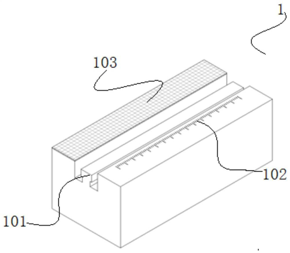
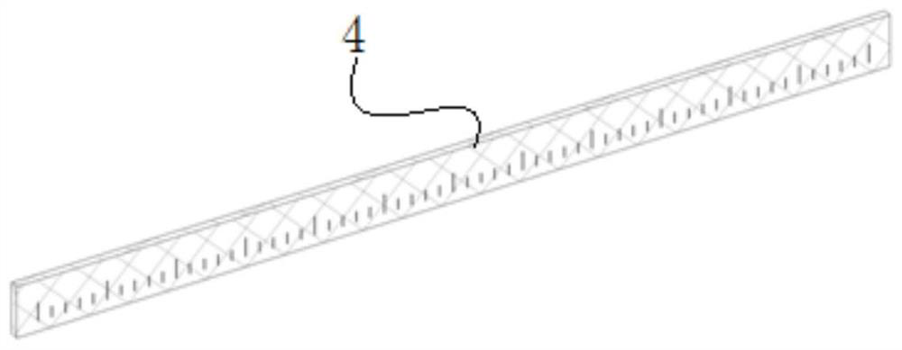
[0055] The upper surface of the base 1 has a track 101 . One side of the track 101 is a rough plane 103 , and the other side has a horizontal scale line 102 . The scale line 102 in the horizontal direction and the scale on the steel ruler 4 can indicate the distance in the horizontal direction of the longitudinal reinforcement.
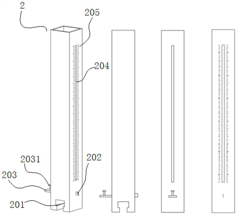
[0056] The lower end of the upright column 2 is a slide groove 201 matched with the track 101 on the base 1 . The column 2 slides along the track 101 . The track 101 is a T-shaped track with a T-shaped cross section. The chute 201 is a T-shaped slot matched with a T-shaped track. The upright 2 has a longitudinal slot 204 passing through both sides, and the two sides pier...
Embodiment 2
[0083] The main structure of this embodiment is the same as that of Embodiment 1, see Figure 7 According to design requirements, two bases 1 and three support frames 6 are configured.
[0084] Two uprights 2 are installed on each base 1 . Each column 2 is equipped with two column connectors 3 up and down. The column connector 3 is configured with a card support 301 having a circular arc support plate I3012.
[0085] Two steel rulers 4 are configured in total. A mobile card support 5 is installed on every steel ruler 4. This mobile card tray 5 has a circular arc supporting plate II502.
[0086] The formed reinforcement cage includes three parallel main reinforcements on the upper and lower sides. Among the three parallel main bars, the two ends of the middle parallel main bar are on the arc supporting plate II502, and the two ends of the two parallel main bars on both sides are on the arc supporting plate I3012.
[0087] Through the scale line 102 in the horizontal direc...
Embodiment 3
[0089] The main structure of this embodiment is the same as that of Embodiment 1, see Figure 8 According to design requirements, two bases 1 and three support frames 6 are configured.
[0090] Two uprights 3 are installed on each base 1 . Each column 2 is equipped with two column connectors 3 up and down. The column connector 3 is configured with a card support 301 having upper and lower arc supporting plates I3012.
[0091] Two steel rulers 4 are configured in total. Two movable clamps 5 are installed on every steel ruler 4 . The mobile card holder 5 has two arc supporting plates II502, upper and lower.
[0092] The formed reinforcement cage includes upper and lower sets of parallel main reinforcements. The upper group of parallel main ribs is divided into upper and lower rows, and each row has five parallel main ribs. Among the five parallel main tendons,
[0093] The two ends of the two parallel main bars on both sides and the middlemost one are on the arc supportin...
PUM
 Abstract
Description
Claims
Application Information
 - R&D
- Intellectual Property
- Life Sciences
- Materials
- Tech Scout
- Unparalleled Data Quality
- Higher Quality Content
- 60% Fewer Hallucinations
Browse by: Latest US Patents, China's latest patents, Technical Efficacy Thesaurus, Application Domain, Technology Topic, Popular Technical Reports.
© 2025 PatSnap. All rights reserved.Legal|Privacy policy|Modern Slavery Act Transparency Statement|Sitemap|About US| Contact US: help@patsnap.com