
Cooling tower with water mist processing device

A technology of a processing device and a cooling tower, applied in the field of cooling towers, can solve problems such as the need to improve the efficiency and the unsatisfactory water mist removal effect, and achieve the effect of saving water sources.

Active Publication Date: 2019-04-16
东营海能石油装备有限责任公司
View PDF6 Cites 3 Cited by
  • Summary
  • Abstract
  • Description
  • Claims
  • Application Information

AI Technical Summary

Problems solved by technology

[0002] In the cooling tower in the prior art, in the process of discharging the steam after heat exchange from bottom to top, it is generally necessary to absorb and condense the excess steam into condensed water through the water collection device, thereby reducing the discharge of water vapor and reducing the water consumption of the cooling tower. and waste of heat, and the water mist treatment device in the prior art can generally use corrugated or S-shaped dewatering plates or other methods to remove water, but due to the heat exchange area and circulation path of the dewatering plates in the prior art The effect of water mist removal is not ideal due to restrictions. Usually, after passing through the water removal device, a large part of water vapor is still discharged directly, and the efficiency needs to be improved.

Method used


Image

  • Cooling tower with water mist processing device
  • Cooling tower with water mist processing device
  • Cooling tower with water mist processing device

Examples


Embodiment Construction

[0028] The following will clearly and completely describe the technical solutions in the embodiments of the present invention with reference to the accompanying drawings in the embodiments of the present invention. Obviously, the described embodiments are only some, not all, embodiments of the present invention. Based on the embodiments of the present invention, all other embodiments obtained by persons of ordinary skill in the art without making creative efforts belong to the protection scope of the present invention.

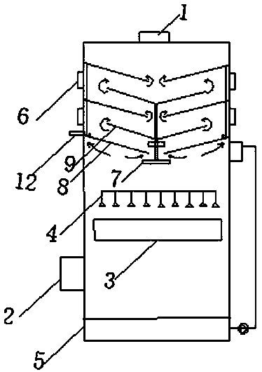
[0029] A cooling tower with a water mist treatment device, including a tower body, a main fan 1, an air inlet 2, a main air outlet, a filler 3, a spray system 4, a water mist treatment device, a pump, a water tank 5, an auxiliary fan 6, and an auxiliary outlet The tuyere, detection system, controller, and water receiving tray 7; wherein, the spray system 4 is a plurality of spray water distribution devices, and there are multiple spray heads; the water mist tre...


PUM


Abstract

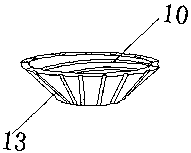
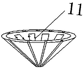
The invention provides a cooling tower with a water mist processing device. The cooling tower can work in different ways and can improve efficiency of water mist. Through first and second mist removing devices which are arranged in a stagger mode, the limited space in the tower can be rationally and fully used. Cone and semicircular cone shapes are arranged in a matched mode. Compared with a traditional s-shaped dewatering plate or a wave-shaped dewatering device, the hear exchange area is enlarged, heat exchanging is improved, and the water mist removing effect is improved. The second mist removing devices are located at the center of the tower body. The second water mist removing devices are adjacent in an up and down mode and communicate with each other by a circulation main pipe. Cooling capacity of fluid can be improved by parallel connection. Through lateral plate mist removing devices on two sides, full heat exchanging effect is achieved to air around the tower body wall. A gridshape is arranged in a matched mode and corresponds to a draught fan outside, and therefore free adjusting and shifting between mist removing and tower body heat exchanging modes can be achieved. Through cooling liquid grooves, circulation water grooves and upper and lower water pipes, a cooling source can be adopted alternatively, water resource is saved, real-time adjusting is conducted based on the temperature requirements, and intelligent temperature control of mist removing is achieved.

Description

technical field [0001] The invention relates to the field of cooling towers, in particular to a cooling tower with a water mist treatment device. Background technique [0002] In the cooling tower in the prior art, in the process of discharging the steam after heat exchange from bottom to top, it is generally necessary to absorb and condense the excess steam into condensed water through the water collection device, thereby reducing the discharge of water vapor and reducing the water consumption of the cooling tower. and waste of heat, and the water mist treatment device in the prior art can generally use corrugated or S-shaped dewatering plates or other methods to remove water, but due to the heat exchange area and circulation path of the dewatering plates in the prior art The effect of water mist removal is not satisfactory due to restrictions. Usually, after passing through the water removal device, a large part of water vapor is still discharged directly, and the efficien...

Claims


Application Information

Patent Timeline
IPC IPC(8): F28C1/16F28F25/00F28F25/02F28F27/00F28F25/10
CPCF28C1/16F28F25/00F28F25/02F28F25/10F28F27/003
Inventor 王长春
Owner 东营海能石油装备有限责任公司
Learn More