

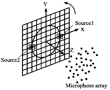
Rotary sound source recognition method based on mixed time frequency domain
A technology of sound source identification and time-frequency domain, applied in voice analysis, instruments, measuring devices, etc., can solve problems such as high sampling frequency, achieve high calculation efficiency, excellent sidelobe suppression, and reduce the effect of sampling frequency in time domain
- Summary
- Abstract
- Description
- Claims
- Application Information
AI Technical Summary
Problems solved by technology
Method used
Image

Examples
Embodiment Construction
[0042] Below in conjunction with accompanying drawing and embodiment the present invention will be further described:
[0043] The present invention comprises the following steps:
[0044] Step 1. Identify the sound source using time-domain tracking Delay and Sum (DAS)
[0045] Assuming that the rotating sound source is at the mth microphone position r at time t m The time-domain sound pressure generated at (m=1,2,3,..., M is the serial number of the microphone) is p(r m ,t).
[0046] Time-domain tracking of the jth scanning grid point on the sound source scanning surface DAS beamforming output b j The time signal of (t) is:
[0047]
[0048] In formula (1), j=1,2,3,...,J, J is the total number of scanning grid points, r j (t) is the position vector of the jth scanning grid point at time t, r mj (t) represents the distance from the mth microphone to the jth scanning grid point at time t, c is the speed of sound; T mj (r m ,r j (t)) represents the transfer function ...
PUM
 Abstract
Description
Claims
Application Information