Optical scanning device and image forming device

An optical scanning device and scanning surface technology, applied in the field of optical scanning, can solve the problems of tilted exposure point, blurred edge of transfer image, and low imaging quality.

Active Publication Date: 2019-04-16
ZHUHAI PANTUM ELECTRONICS
View PDF5 Cites 4 Cited by
  • Summary
  • Abstract
  • Description
  • Claims
  • Application Information

AI Technical Summary

Problems solved by technology

[0004] However, if the maximum scanning incident angle of the beam incident on the photosensitive drum is too large, the position of the exposure point at both ends of the edge of the photosensitive drum...

Method used


Image

  • Optical scanning device and image forming device
  • Optical scanning device and image forming device
  • Optical scanning device and image forming device

Examples


Embodiment Construction

[0046] In order to make the purpose, technical solutions and advantages of the embodiments of the present invention clearer, the technical solutions in the embodiments of the present invention will be clearly and completely described below in conjunction with the drawings in the embodiments of the present invention. Obviously, the described embodiments It is only some embodiments of the present invention, but not all embodiments. Based on the embodiments of the present invention, all other embodiments obtained by persons of ordinary skill in the art without making creative efforts belong to the protection scope of the present invention.

[0047] In addition, the terms "first" and "second" are used for descriptive purposes only, and cannot be interpreted as indicating or implying relative importance or implicitly specifying the quantity of indicated technical features. Thus, a feature defined as "first" and "second" may explicitly or implicitly include one or more of these feat...


PUM


Abstract

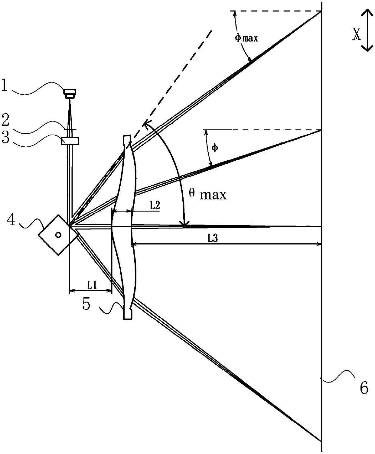
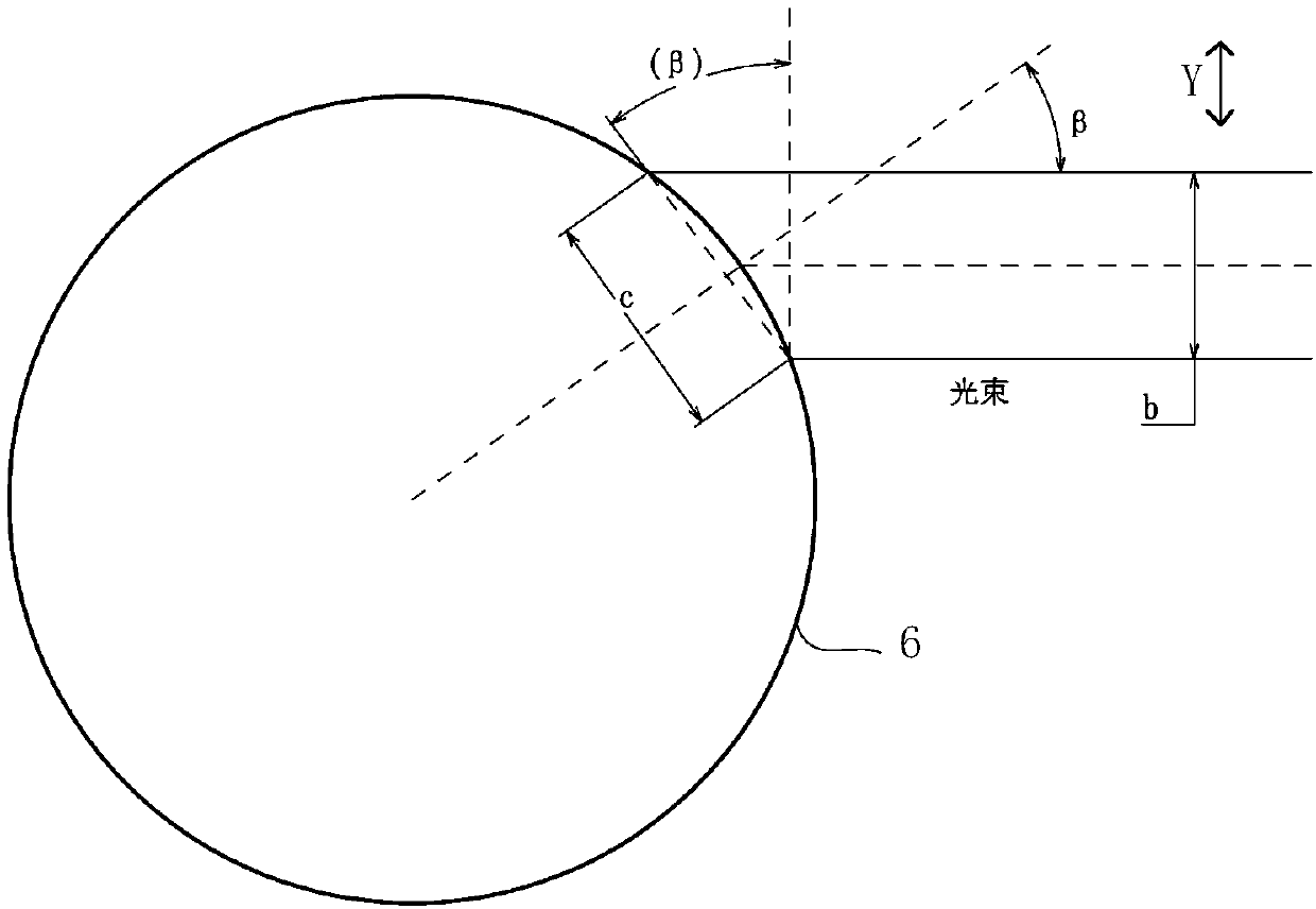
The invention provides an optical scanning device and an image forming device. The optical scanning device comprises a light source used for diverging a light beam, a first optical unit used for enabling the light beam emitted by the light source to be collimated in a main scanning direction and to be focused in an auxiliary scanning direction, an optical deflector used for deflecting the light beam emitted by the light source, and an imaging optical system used for guiding the light beam deflected by the optical deflector to a scanned surface to be imaged. When the optical deflector is used for deflecting the light beam emitted by the light source at a maximum deflection angle, the emergent light beam of the imaging optical system forms a maximum incident included angle phi max together with a normal line of the scanned surface in the main scanning direction, and the light spot inclination rate, defined in the description, of a light spot formed on the scanned surface by the imaging optical system meets a condition defined in the description, so that the possibility of edge blur of a transfer image is reduced, and the optical scanning imaging quality is improved.

Description

technical field [0001] The present invention relates to optical scanning technology, in particular to an optical scanning device and an image forming device. Background technique [0002] Optical scanning equipment is widely used in image forming fields such as printing and imaging, graphic copying, laser coding and medical imaging. For example, in printers or copiers that form images on recording media, an optical scanning device is used to scan the scanned surface of the photosensitive drum to form an electrostatic latent image, which is then developed and transferred to the paper surface for printing or copying. However, the size of the optical scanning device has a great influence on the volume of the overall product. In order to reduce the volume of the overall product, it is necessary to realize the miniaturization of the optical scanning device on the premise of ensuring the scanning accuracy and scanning quality. [0003] In the existing optical scanning equipment, ...

Claims


Application Information

Patent Timeline
IPC IPC(8): G02B26/10G03G15/04
CPCG02B26/105G03G15/04036G02B26/12G02B26/101G02B26/121G02B26/125G03G15/043
Inventor 王超邵哲
Owner ZHUHAI PANTUM ELECTRONICS
Why Eureka
Try Eureka