An Optimization Method for Low-Temperature Thermal System

An optimization method and low-temperature thermal technology, applied in the petrochemical field, can solve problems such as slow solution speed, solution speed and accuracy cannot meet the complex and changeable low-temperature thermal system, and achieve rapid optimization speed, good economic benefits and energy-saving effects, and reduce operating costs. cost effect

Active Publication Date: 2022-05-06
石化盈科信息技术有限责任公司
View PDF4 Cites 0 Cited by
  • Summary
  • Abstract
  • Description
  • Claims
  • Application Information

AI Technical Summary

Problems solved by technology

However, the sequential module method to solve the complex process model needs to continuously cut off the recirculation stream to reduce the order, the solution speed is slow, and there is a certain gap between the calculation results and the actual site, and the solution speed and accuracy are far from meeting the complex and changeable actual operating conditions of the low-temperature thermal system.

Method used


Image

  • An Optimization Method for Low-Temperature Thermal System
  • An Optimization Method for Low-Temperature Thermal System
  • An Optimization Method for Low-Temperature Thermal System

Examples


Embodiment 1

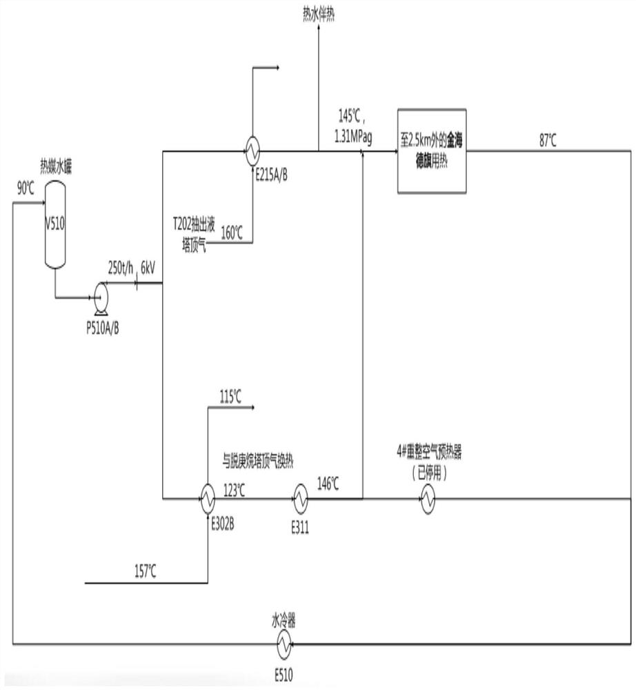
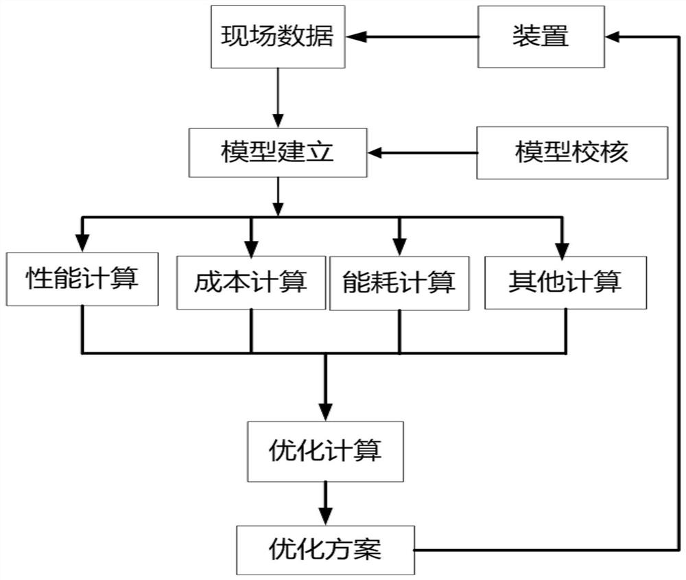
[0098] The first step is to collect and sort out the basic operating data, establish the basic mechanism model of the low-temperature thermal system, and simulate the actual working conditions.

[0099] In this step, according to four sets of low-temperature thermal systems of a refining and chemical enterprise (such as figure 1 As shown), sort out the operating condition data of heat sources and heat sinks, verify the flow chart of low-temperature heat, establish the mechanism model of low-temperature heat flow, and calculate the parameters of medium physical properties and temperature.

[0100] Specifically:

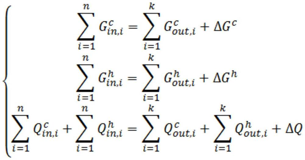
[0101] (1) Based on the actual low-temperature heat process and data, including the flow, temperature and pressure data of the heat source, and the flow, temperature and pressure data of the heat sink, confirm the flow direction, heat transfer mode and other processes of the low-temperature heat source and heat sink, Establish mathematical mechanism models of four low...


PUM


Abstract

The invention relates to an optimization method of a low-temperature thermal system, comprising the following steps: establishing a mathematical mechanism model of a low-temperature thermal system; establishing an optimization model of a low-temperature thermal system by using a simultaneous module method; The optimization model of the system is solved. This method greatly improves the solution speed of the constrained multi-variable low-temperature thermal system model optimization problem in the chemical industry, and better solves the problem that the existing mathematical solution model cannot quickly and accurately simulate and optimize the low-temperature thermal system. The optimization scheme generated by this method is more in line with the actual situation of the enterprise, and the energy saving effect is more significant.

Description

technical field [0001] The invention belongs to the petrochemical field, and in particular relates to an optimization method for a low-temperature thermal system. Background technique [0002] The rapid development of the global economy, the growth of population, and the continuous increase in energy consumption have created a tense energy situation. In the face of the gradually depleted primary energy (coal, oil, natural gas, nuclear energy), no reasonable substitute has been found at this stage. Therefore, developing new energy and improving the utilization rate of primary energy is one of the ways to solve the current energy crisis. However, there are still many problems in the utilization of new energy sources such as solar energy, geothermal energy, nuclear energy, biomass energy, and wind energy that have not been effectively resolved, and it is difficult to undertake the heavy responsibility of alternative energy sources. Therefore, improving the utilization rate of ...

Claims


Application Information

Patent Timeline
Patent Type & Authority Patents(China)
IPC IPC(8): G06Q10/04G06Q50/02G06F30/20G06F119/08
CPCG06Q10/04G06Q50/02G06F2119/08G06F30/20Y02P80/10
Inventor 裴旭关新虎焦云强王建平邸雪梅朱贤琨
Owner 石化盈科信息技术有限责任公司
Why Eureka
Try Eureka