
Inverse Scott transformer

A Scott transformer, low-voltage coil technology, applied in the direction of transformers, variable transformers, transformer/inductor components, etc., can solve problems such as resistance unbalance, and achieve the effect of resistance balance

Pending Publication Date: 2019-04-16
CHONGQING KEXIN ELECTRIC CO LTD
View PDF0 Cites 2 Cited by
  • Summary
  • Abstract
  • Description
  • Claims
  • Application Information

AI Technical Summary

Problems solved by technology

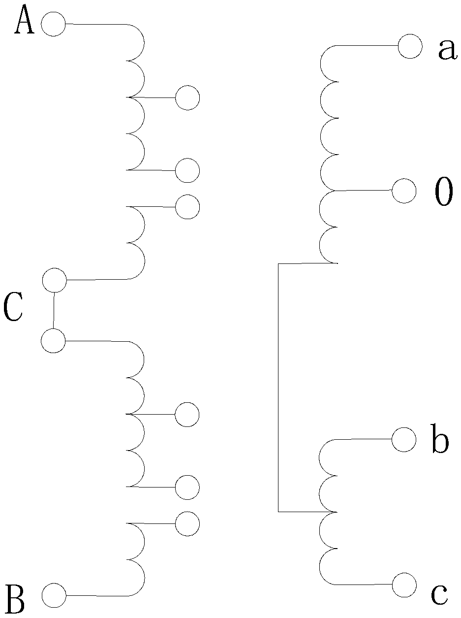
[0006] The purpose of the present invention is to provide an inverse Scott transformer in view of the problem of unbalanced resistance when the low-voltage coil of the M transformer is wound with multiple wires in the prior art.

Method used


Image

  • Inverse Scott transformer
  • Inverse Scott transformer
  • Inverse Scott transformer

Examples


Embodiment 1

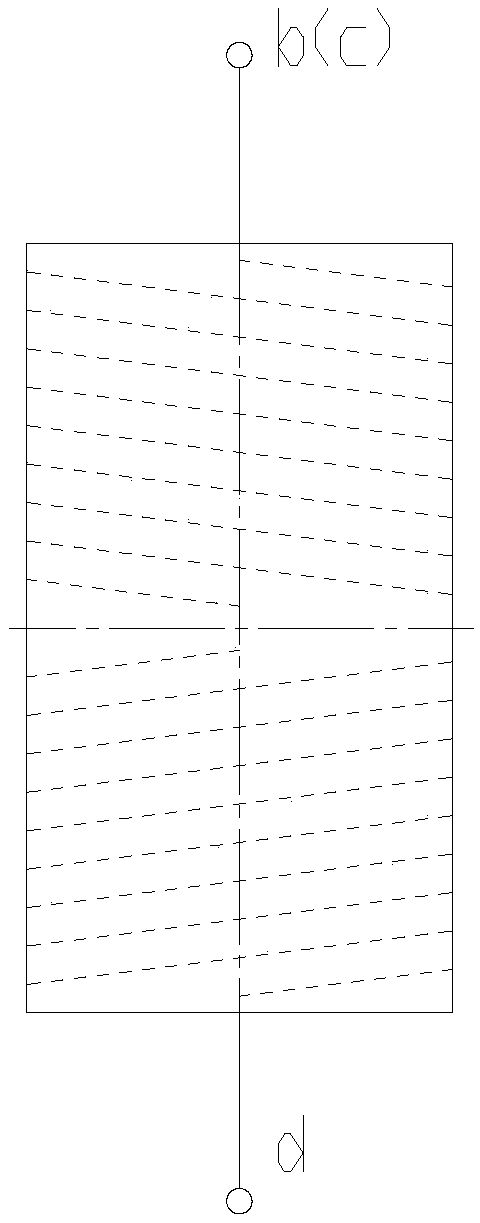
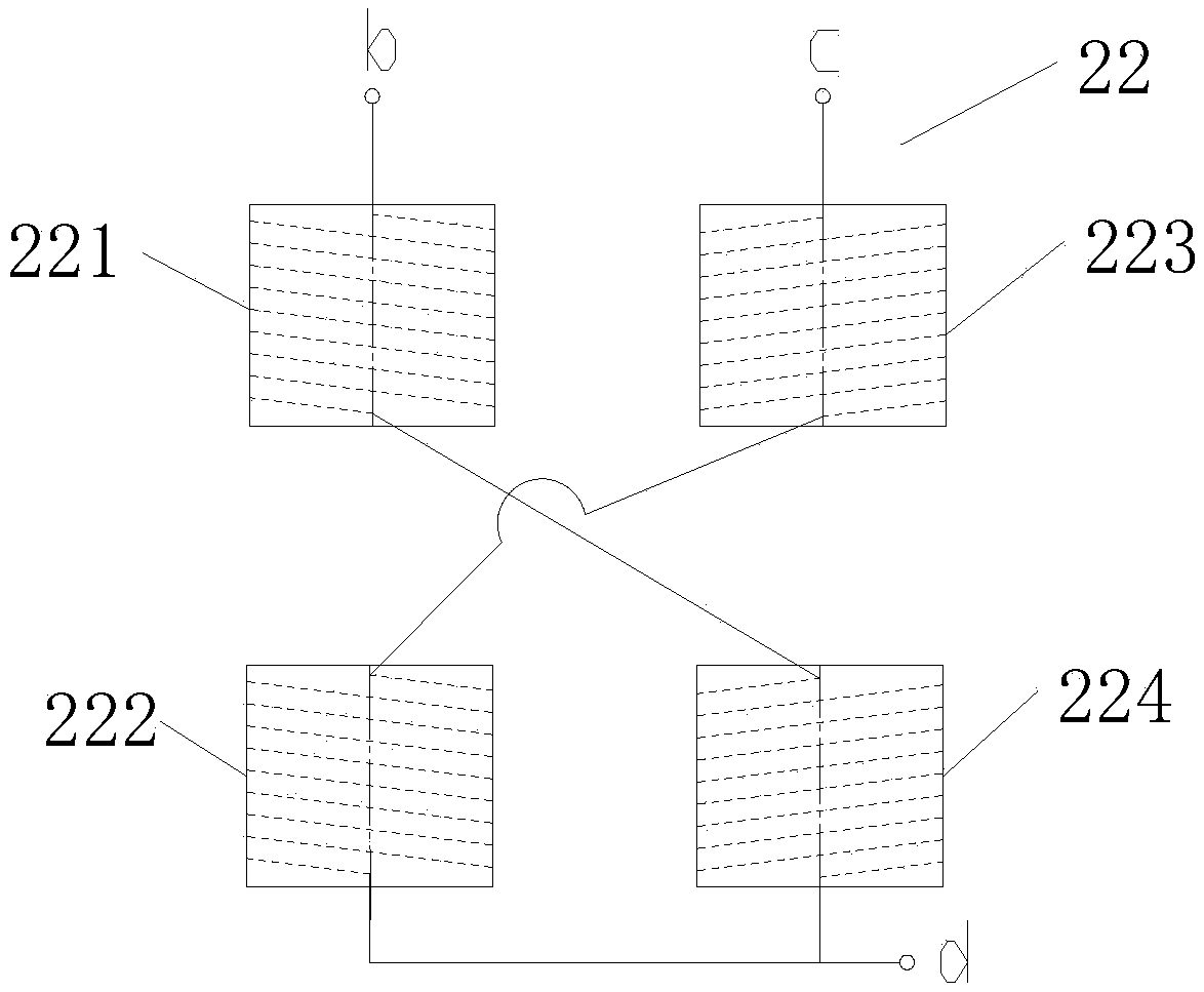
[0027] The number of turns of the first winding 221, the second winding 222, the third winding 223, and the fourth winding 224 of the M variable voltage coil 22 is 26 turns, and the first winding 221 and the fourth winding 224 are connected in series, and the first winding 221 The wires are wound in a clockwise direction, and the fourth winding 224 is wound in a counterclockwise direction. The second winding 222 and the third winding 223 are connected in series, the second winding 222 is wound in a clockwise direction, and the third winding 223 is wound in a counterclockwise direction. Therefore, the number of winding turns of the b-phase in the M variable low-voltage coil 22 is 52 turns, and the number of winding turns of the c-phase is 52 turns. By the winding method provided by the application, the winding circumferences of the b-phase and the c-phase are the same, thus Phase b and phase c have the same resistance, the fourth winding 224 of phase b is connected to the secon...


PUM


Abstract

The invention provides an inverse Scott transformer. The inverse Scott transformer comprises a support, an M-transformer iron core and a T-transformer iron core, wherein the M-transformer iron core and the T-transformer iron core are disposed on the support. An M-variable high-voltage coil and an M-transformer low-voltage coil are arranged outside the M-transformer iron core, and a T-transformer high-voltage coil and a T-transformer low-voltage coil are arranged outside the T-transformer iron core. The M-transformer high-voltage coil is connected with the T-transformer high-voltage coil in series. The windings of the M-transformer low-voltage coil comprise a first winding, a second winding, a third winding and a fourth winding. The third winding is wound outside the first winding, and thefourth winding is wound outside the second winding. The first winding and the fourth winding are opposite in a winding direction, and the second winding and the fourth winding are opposite in a winding direction. The first winding is connected with the fourth winding, and the third winding is connected with the second winding. The four windings have the same number of turns. A winding of the M-transformer low-voltage coil is divided into four sections, wherein one section of two sections of the winding at the same phase is located at the inner side of the coil and the other one of the two sections of the winding at the same phase is located outside the coil, and standard transposition is carried out from the first layer to the second layer, thereby guaranteeing that the lengths of the windings of two phases in the M-transformer low-voltage coil are the same, and achieving the resistance balance.

Description

technical field [0001] The invention relates to the technical field of transformers, in particular to an inverse Scott transformer. Background technique [0002] Traction power supply systems for electrified railways mainly include direct supply mode and autotransformer (Auto Transformer, AT) power supply mode. The disadvantages of the direct supply method are short power supply distance, large number of split phases, and poor power supply quality; the AT power supply method can increase the power supply voltage, extend the power supply distance, reduce line loss, and effectively reduce the interference of the AC traction network on the communication line. There are some advantages in powering the load. [0003] The inverse Scott transformer is a special transformer that can convert the two-phase power (two single-phase phases with a phase difference of 90°) of the power supply (referred to as the road network) into three-phase power, that is, the side of the traction stati...

Claims


Application Information

Patent Timeline
Patent Type & Authority Applications(China)
IPC IPC(8): H01F29/00H01F27/00H01F27/30
CPCH01F27/006H01F27/306H01F29/00
Inventor 周燕
Owner CHONGQING KEXIN ELECTRIC CO LTD
Learn More