Operation rod maintenance type integrated intelligent high-voltage switch

A high-voltage switch, one-piece technology, applied to switches operated by live operating rods, electric switches, high-voltage air circuit breakers, etc., can solve the difficulty of linkage testing between the switch part and the intelligent part, which affects the comprehensiveness and reliability of intelligence Sexuality, intelligent micro-signal damage and other problems, to achieve the effect of high cost performance, simple structure and convenient operation

Active Publication Date: 2019-04-16
JIANGSU MODERN POWER CAPACITOR
View PDF6 Cites 2 Cited by
  • Summary
  • Abstract
  • Description
  • Claims
  • Application Information

AI Technical Summary

Problems solved by technology

[0004] The existing intelligent high-voltage switch installs the switch part and the intelligent part separately and uses cables to connect each other, which will damage many micro-signals used for intelligence circulating between the two, and affect the overall

Method used


Image

  • Operation rod maintenance type integrated intelligent high-voltage switch
  • Operation rod maintenance type integrated intelligent high-voltage switch
  • Operation rod maintenance type integrated intelligent high-voltage switch

Examples


Embodiment 1

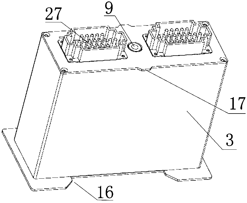
[0029] Such as image 3 with Figure 4 As shown, the structure of the locking mechanism is that the upper end of the rotating shaft 6 is provided with a threaded hole 9 opened in the vertical direction, and a bolt 10 is fixed on the upper side of the chamber 5, and the bolt 10 is arranged in the vertical direction and the upper end of the bolt 10 is fixed in the chamber. On the upper side of the cavity 5, the position of the bolt 10 corresponds to the threaded hole 9 at the upper end of the rotating shaft 6. When the intelligent module 3 is inserted into the cavity 5, the lower end of the bolt 10 is inserted into the threaded hole 9 at the upper end of the rotating shaft 6 and threaded with the rotating shaft 6. connect.

Embodiment 2

[0031] The structure of the locking mechanism is that the upper end of the rotating shaft is provided with two pin shafts, the two pin shafts are arranged along a radial direction of the cross section of the rotating shaft, and one end of the two pin shafts is respectively fixed on the sides of the upper end of the rotating shaft. A sleeve is fixed on the upper side, and a blind hole matching the rotating shaft is arranged in the sleeve. An annular groove is opened in the blind hole, and two concave holes matching the pin shaft are arranged on both sides of the blind hole along a radial direction. Groove, the upper end of the groove communicates with the annular channel. When the intelligent module is inserted into the cavity, the pin shaft at the upper end of the rotating shaft is inserted into the annular channel from the groove and rotated 90 degrees to lock and fix. The inner wall of the annular channel is at the position where the pin rotates 90 degrees. A baffle is provid...


PUM


Abstract

The invention discloses an operation rod maintenance type integrated intelligent high-voltage switch. The high-voltage switch comprises a mainframe box, an auxiliary box, an intelligent module and a module operating rod. A three-pole switch is arranged in the mainframe box. The auxiliary box is fixed on one side of the mainframe box. An opening is formed in the lower side of the auxiliary box. Anaccommodating cavity matched with the intelligent module is formed in the auxiliary box. A socket or a plug, which are matched with each other, are arranged on the upper side of the intelligent moduleand the upper side face of the accommodating cavity. A rotating shaft is rotationally arranged in the middle of the intelligent module in the vertical direction. Locking mechanisms matched with eachother are arranged at the upper end of the rotating shaft, and the upper side, corresponding to the upper end of the rotating shaft, of the accommodating cavity. An intelligent module clamp is rotationally arranged at the upper end of the module operating rod. Locking structures matched with each other and used for preventing the module operating rod and the accommodating cavity from rotating circumferentially are arranged at the corresponding positions of the upper end of the module operating rod and the accommodating cavity. The intelligent module and the high-voltage switch are arranged together, thus being convenient in maintenance.

Description

technical field [0001] The invention relates to an intelligent high-voltage switch, in particular to an integrated intelligent high-voltage switch of a joystick maintenance type. Background technique [0002] The intelligent switch used in the power grid is generally composed of two parts. One part is the switch part of high voltage and high current, which is used to connect or isolate the power grid; the other part is the intelligent part of micro voltage and micro current, which realizes the intelligent functions of measurement, protection, control, signal, diagnosis and communication of the switch . There are transition devices such as sensors and actuators between the switch part and the intelligent part, and these transition devices are generally installed in the switch part. [0003] The switch part and the intelligent part of the existing high-voltage intelligent switch are separated from each other, and the two are installed in different places or positions, and ar...

Claims


Application Information

Patent Timeline
IPC IPC(8): H01H31/00H01H31/02
CPCH01H31/006H01H31/02
Inventor 施文冲王春华纪陈平吴骏顾勇姚卫东宋玉锋申海群潘丽平
Owner JIANGSU MODERN POWER CAPACITOR
Why Eureka
Try Eureka