
Flame-assisted fuel cell power generation and heat supply device

A kind of technology of fuel cell and heating device

Inactive Publication Date: 2019-04-16
JIANGSU UNIV
View PDF4 Cites 0 Cited by
  • Summary
  • Abstract
  • Description
  • Claims
  • Application Information

AI Technical Summary

Problems solved by technology

However, since the fuel cell is directly in contact with the flame, a thermal gradient will be formed on the fuel cell, and the low power generation efficiency of the flame fuel cell is also a challenge so far.

Method used


Image

  • Flame-assisted fuel cell power generation and heat supply device
  • Flame-assisted fuel cell power generation and heat supply device

Examples


Embodiment Construction

[0019] In order to make the object, technical solution and advantages of the present invention clearer, the present invention will be further described in detail below in conjunction with the accompanying drawings and embodiments. It should be understood that the specific embodiments described here are only used to explain the present invention, not to limit the present invention.

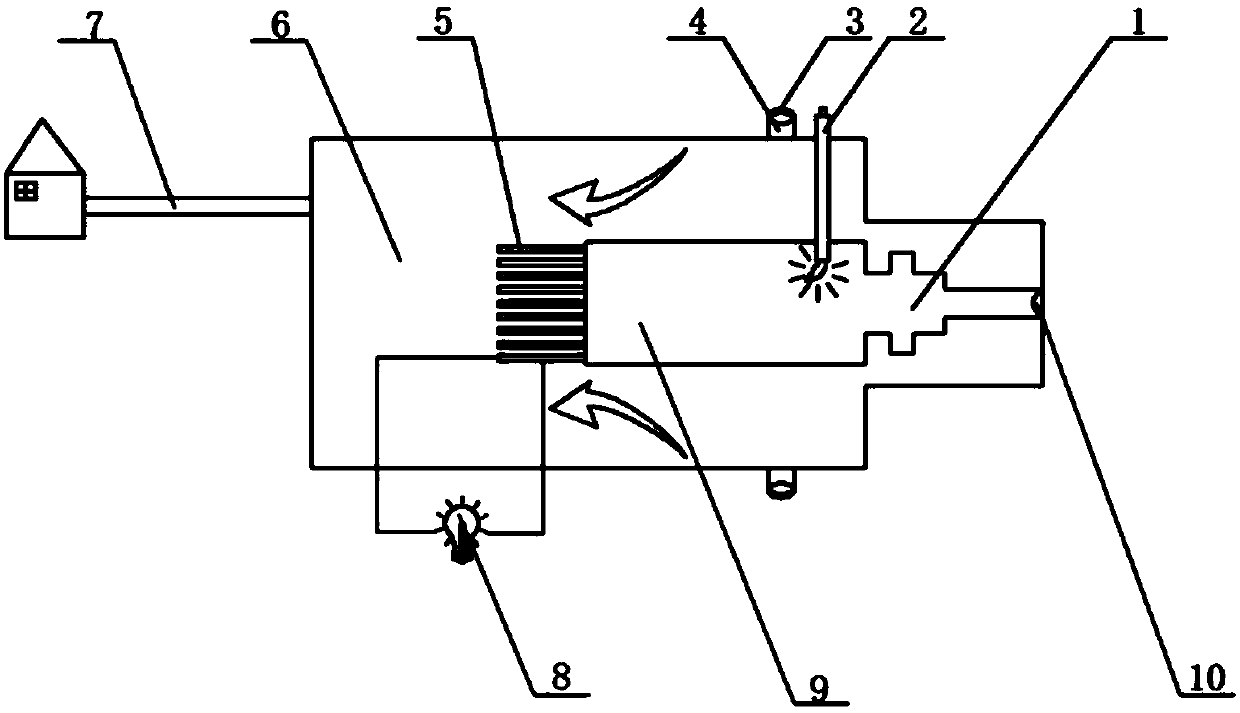
[0020] like figure 1 As shown, a flame-assisted fuel cell power generation and heating device proposed by the present invention includes a premixed combustion device 1, a rich combustion device 9 and a fuel cell power generation device 5 connected in sequence, and the premixed combustion device 1, the rich combustion The device 9 and the fuel cell power generation device 5 are placed in the cavity of the lean-burn combustion device 6 as a whole, and a mixed gas input pipe is provided at one end of the pre-mixed combustion device 1, and the mixed gas input pipe passes through the lean-burn combustio...


PUM

PropertyMeasurementUnit
diameteraaaaaaaaaa
lengthaaaaaaaaaa

Abstract

The invention discloses a flame-assisted fuel cell power generation and heat supply device, comprising a premixed combustion device, a rich combustion device and a fuel cell power generation device which are sequentially connected, wherein the premixed combustion device, the rich combustion device and the fuel cell power generation device are arranged in a cavity of a lean combustion device; a mixed gas input pipe is arranged at the end of the premixed combustion device, and the input pipe passes through one side end surface of the lean combustion device; a flow controller B is arranged on theinput pipe, an ignition device radially extending into a cavity of the rich combustion device is arranged on a shell of the lean combustion device, a plurality of air inlets are uniformly arranged onthe shell of the lean combustion device close to the ignition device, and a flow controller A is arranged on the air inlets; a heat transfer pipeline is arranged on the other side end surface of thelean combustion device; and the fuel cell power generation device is connected to an electric appliance. The scheme of the invention can effectively solve the problem that the residual fuel at the tail end of the fuel cell is not fully utilized.

Description

technical field [0001] The invention belongs to the technical field of flame combustion batteries, in particular to a flame-assisted fuel cell power generation and heat supply device. Background technique [0002] In a traditional flame fuel cell, the solid oxide cell is in direct contact with a rich flame, and the flame provides the cell with both fuel and the temperature required for operation, while the cathode is in direct contact with the ambient air. Compared with solid oxide fuel cells, flame fuel cells have a simpler structure and smaller volume, and can be used in more environmental conditions. Moreover, rich combustion provides heat without additional heating devices, so that the time required for the start and stop of the flame fuel cell is shorter. However, since the fuel cell is directly in contact with the flame, a thermal gradient will be formed on the fuel cell, and the low power generation efficiency of the flame fuel cell is also a challenge so far. [00...

Claims


Application Information

Patent Timeline
Patent Type & Authority Applications(China)
IPC IPC(8): H01M8/04014H01M8/04089
CPCH01M8/04022H01M8/04089Y02E60/50
Inventor 何志霞王欣冯永强王谦
Owner JIANGSU UNIV
Learn More