
Metamaterial antenna cover and antenna system

A radome and metamaterial technology, applied in the field of metamaterials, can solve problems such as no cut-off characteristics, wide operating bandwidth, and inability to meet application requirements.

Inactive Publication Date: 2019-04-16
AEROSPACE SCI & IND WUHAN MAGNETISM ELECTRON
View PDF9 Cites 14 Cited by
  • Summary
  • Abstract
  • Description
  • Claims
  • Application Information

AI Technical Summary

Problems solved by technology

[0003] The microstructure of traditional radome metamaterials usually adopts a single-screen nested structure, which can achieve band-pass transmission characteristics within the working frequency band, but its biggest disadvantage is that the working bandwidth is not wide and there is no cut-off characteristic. For some applications, broadband selection is required. frequency extremely strict and steep cut-off, this metamaterial cannot meet the application requirements

Method used


Image

  • Metamaterial antenna cover and antenna system
  • Metamaterial antenna cover and antenna system
  • Metamaterial antenna cover and antenna system

Examples


no. 1 example

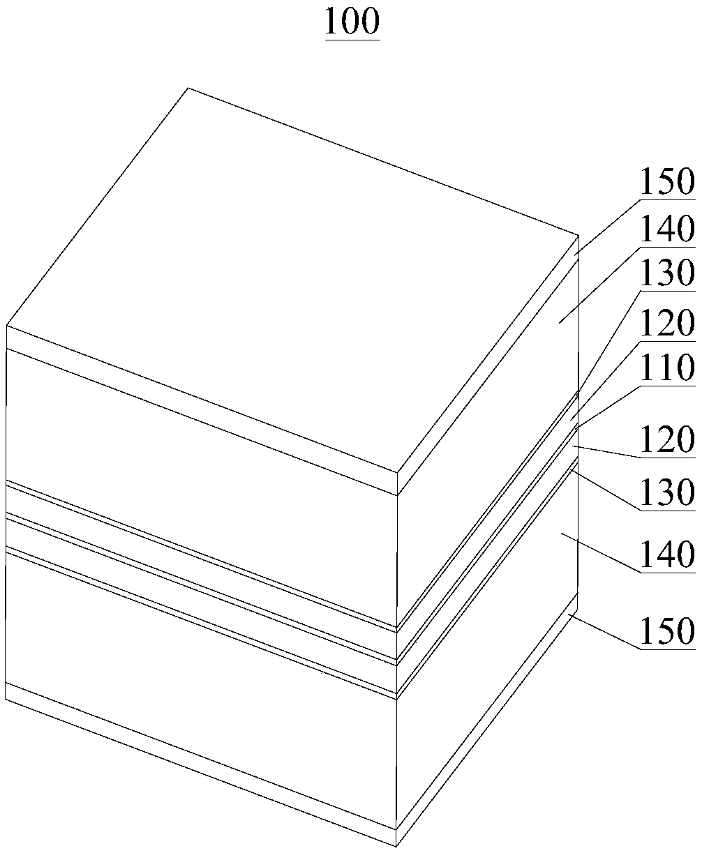
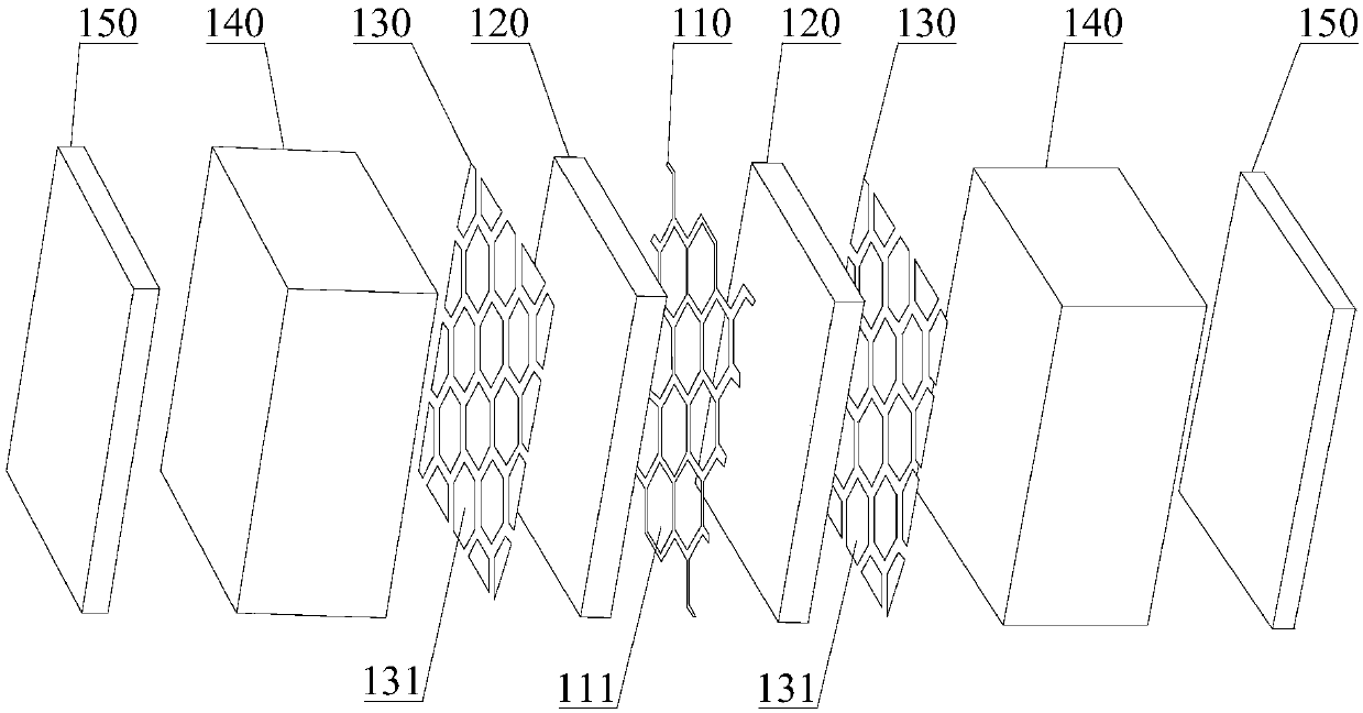
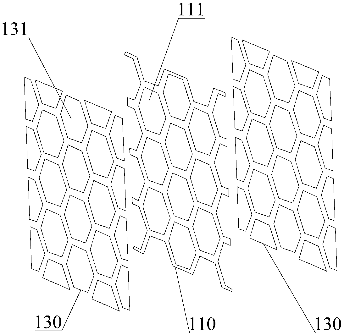
[0040] Please refer to figure 1 and figure 2 , the present embodiment provides a metamaterial radome 100, which includes two layers of dielectric substrates 150 stacked, and a first metal layer 110 stacked between the two layers of dielectric substrates 150, the first metal layer 110 and each layer of dielectric The second metal layer 130 is stacked between the substrates 150, the first sandwich layer 120 is stacked between the first metal layer 110 and each layer of the second metal layer 130, and each layer of the dielectric substrate 150 is connected to the adjacent A second sandwich layer 140 is arranged between the second metal layers 130, the first metal layer 110 has a plurality of identical and spaced hollows 111, the second metal layer 130 is mainly composed of a plurality of identical metal patches 131, There is a gap between two adjacent metal patches 131 , and each metal patch 131 of the second metal layer 130 is in one-to-one correspondence with the hollows 111 ...

no. 2 example

[0057] This embodiment provides an antenna system, which includes an antenna body and the above-mentioned metamaterial radome 100, and the metamaterial radome 100 is arranged at a distance from the antenna body.

[0058] In this embodiment, the antenna body may include, but is not limited to, equipment that needs to emit or receive electromagnetic waves in a specific band, such as a radiation source, a feeding unit, and the like.

[0059] In summary, the metamaterial radome and the antenna system of the embodiment of the present invention integrate wave transmission and wave absorption to achieve efficient wave transmission within the working frequency band and wave absorption outside the working frequency band.


PUM


Abstract

The invention provides a metamaterial antenna cover and an antenna system and relates to the technical field of metamaterials. The metamaterial antenna cover comprises two layers of dielectric substrates which are arranged in a stack manner and a first metal layer arranged between the two layers of dielectric substrates in a stack manner, wherein a second metal layer is respectively arranged between the first metal layer and each layer of the dielectric substrates in a stack manner; a first sandwich layer is further respectively arranged between the metal layer and each of the second metal layers in a stack manner; the first metal layer has a plurality of same hollows which are distributed at intervals; the second metal layers are mainly composed of a plurality of same metal patches; and metal patches of the second metal layers have an one-to-one correspondence with the hollows of the first metal layer. The antenna system comprises an antenna body and the metamaterial antenna cover which are arranged at intervals. Through the metamaterial antenna cover and the antenna system, which are provided by the invention, the wave transmission and the wave absorption are integrated and the purposes of carrying out high-efficiency wave transmission within a working frequency band and carrying out wave absorption outside the working frequency band are achieved.

Description

technical field [0001] The invention relates to the technical field of metamaterials, in particular to a metamaterial radome and an antenna system. Background technique [0002] Metamaterial is a kind of artificial electromagnetic functional material, and its basic unit is a mesoscopic microstructure between macroscopic and microscopic. Under normal circumstances, the antenna system will be equipped with a radome. The function of the radome is to protect the antenna system from the influence of wind, rain, snow, sand and solar radiation, so that the performance of the antenna system is relatively stable and reliable, and at the same time reduce the wear and tear of the antenna system. , Corrosion and aging, prolong service life. Due to the particularity of the metamaterial, when the metamaterial is applied to the radome, the radome can have a bandpass transmission characteristic in the working frequency band of the own radar, which can reduce the radar cross section (RadarC...

Claims


Application Information

Patent Timeline
Patent Type & Authority Applications(China)
IPC IPC(8): H01Q1/42H01Q15/00
CPCH01Q1/422H01Q1/424H01Q15/0026H01Q15/0086
Inventor 王俊鹏王绪超夏云龙昌尹生明鹏彭学刚谢云丁庚常明阳汪均鉴胡俊李坤何惊华
Owner AEROSPACE SCI & IND WUHAN MAGNETISM ELECTRON
Learn More